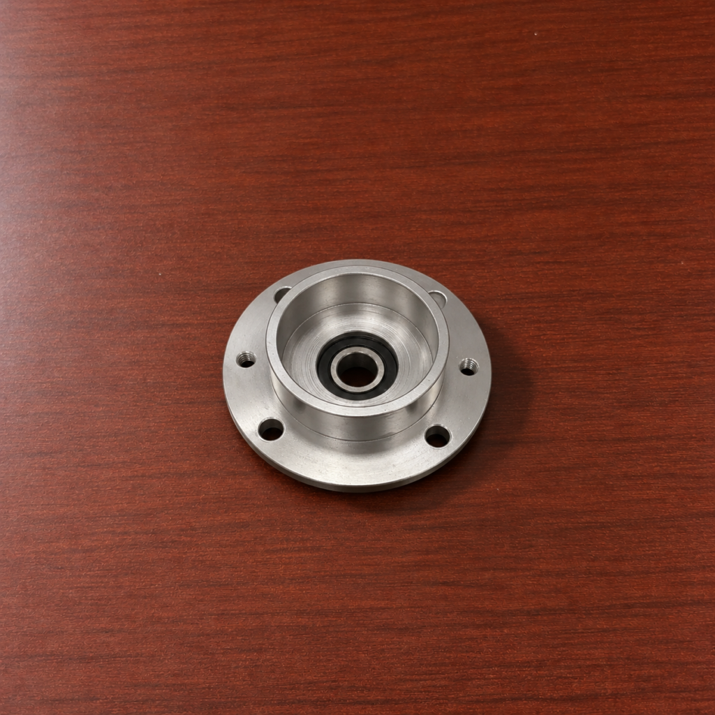

Instrument knob CNC machining must coordinate the surface touched by the operator with the bore that connects the part to a control shaft. The visible body may contain a straight, tapered or stepped profile, while the mounting end can include a round bore, flat, thread or locking-screw hole.
Producing these features from one rotational reference keeps the knob centered when it is assembled and turned.
Shape the Knob Body
The blank is faced to establish the front reference. Rough turning then forms the main outside diameter and removes stock from any steps, tapers or recessed sections.
The finishing tool follows the complete external profile with a consistent feed. Decorative grooves or a narrow indicator feature may be added during the same setup.
Enough material is left on the grip area when knurling will displace the surface outward. This prevents the finished knurled diameter from becoming larger than the design allows.
Form the Grip Pattern
Knurling does not remove material in the same way as ordinary turning. The knurl wheels press a repeated pattern into the rotating surface, producing a grip around the knob.
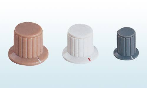
Straight knurling creates parallel ridges, while diamond knurling produces a crossed pattern. Tool alignment is important because an incorrectly positioned wheel may overlap the pattern and create irregular teeth.
The knurling tool approaches gradually until the full pattern is established. Coolant helps reduce material buildup and clears loose particles from the contact area.
A short finishing pass may be used on the adjacent shoulders after knurling, but the grip surface itself is normally left with its formed texture.
Open the Center Bore
The axial hole begins with center drilling, followed by drilling close to the required size. The final operation depends on how the knob attaches to its shaft:
| Mounting feature | Machining method |
|---|---|
| Round shaft bore | Drilling and reaming |
| Threaded connection | Drilling and tapping |
| D-shaped bore | Drilling, boring and milling |
| Blind mounting bore | Controlled-depth drilling and boring |
Boring can correct the drilled hole relative to the spindle axis. Reaming is useful when a consistent cylindrical fit is required along the full bore length.
For a blind bore, chip evacuation must be controlled so material does not collect at the bottom and reduce the available assembly depth.
Add the Locking Feature
Many instrument knobs use a radial set screw to hold the knob on the shaft. After the turned features are complete, the spindle indexes the part so the side hole can be spot drilled, drilled and tapped.
The radial hole must intersect the mounting bore at the intended position. If the knob uses a D-shaped bore, the locking screw is usually oriented in relation to the internal flat.
Turn-mill equipment can complete this operation without removing the knob from the original spindle. A secondary fixture may also locate the part from its finished bore or outer diameter.
Complete the Second End
After parting, the knob is reversed to finish the rear face and bring the component to final length. Soft jaws or a collet protect the completed external profile and knurling.
Burrs are removed from the bore entrance, side thread and turned edges without softening the grip pattern. Effective instrument knob CNC machining keeps the external body, tactile surface and shaft connection centered through a compact sequence of turning, forming and hole-making operations.