The Seal Face Was Finished—Then It Was Blasted
Blasting masking becomes critical when a machined sealing face must remain smooth after surface treatment.
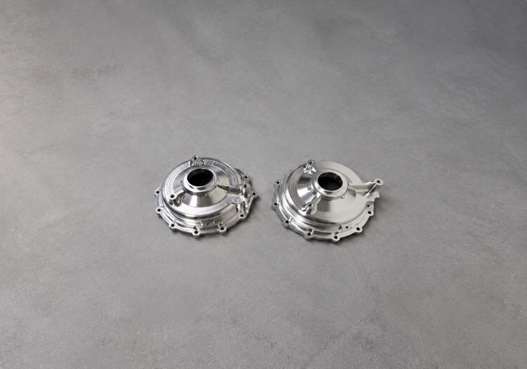
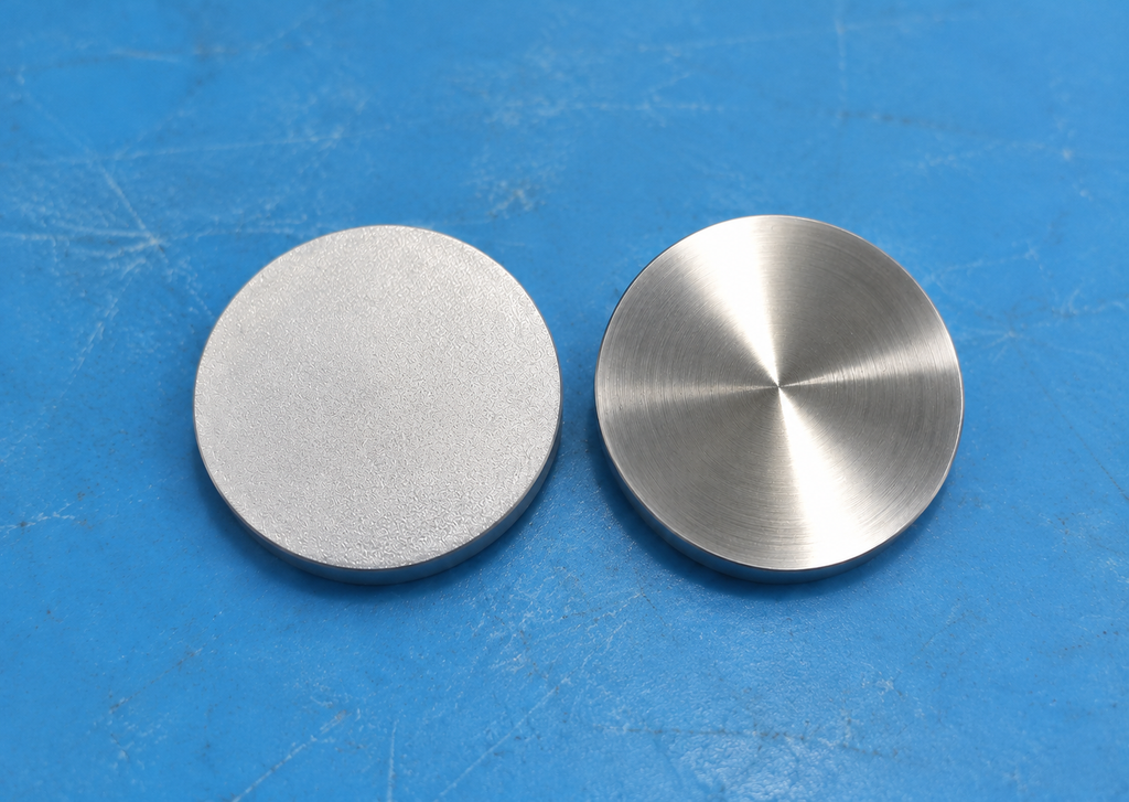
A housing cover had passed final inspection. Its gasket land met the required roughness and flatness, and the mating part assembled correctly. After blasting, the component looked clean and uniform—but the sealing surface no longer met its roughness requirement.
The problem was not the blasting operation alone. The drawing identified the sealing face, but it did not clearly define the area that had to be protected from abrasive media.
A note such as “mask sealing surface” is often too vague for production and inspection. The drawing must show exactly what is excluded, where the boundary lies, and what condition is required after blasting.
Identify the Functional Surface First
The sealing face should be identified directly on the drawing with a leader, surface-texture requirement, and any applicable flatness or profile control.
Do not rely on a general note or an assembly drawing to communicate the requirement. The machinist, blasting supplier, and inspector must all be able to identify the controlled surface from the part drawing.
If only part of a face seals, define that exact land or annular area. If the entire flange face seals, make that clear as well.
Define the Masking Boundary with Dimensions
Show the blasting exclusion zone with a closed boundary line, detail view, or section view. Dimension the boundary from functional datums, bore centers, outside diameters, or other stable reference features.
Avoid vague notes such as “Mask all critical surfaces.” They leave too much room for interpretation during blasting and inspection.
Instead, define the mask edge with a measurable limit. Identify the sealing land and specify how far the protected area must extend beyond the gasket contact line or groove. Set this extension according to the gasket design, assembly position, and risk of abrasive-media spread.
For internal bores, counterbores, and grooves, state whether the entire feature must be masked or only a defined sealing band.
Define the Masking Boundary with Dimensions
Show the blasting exclusion zone with a closed boundary line, detail view, or section view. Dimension the boundary from functional datums, bore centers, outside diameters, or other stable reference features.
Avoid vague notes such as “Mask all critical surfaces.” They leave too much room for interpretation during blasting and inspection.
Instead, define the mask edge with a measurable limit. Identify the sealing land and specify how far the protected area must extend beyond the gasket contact line or groove. Set this extension according to the gasket design, assembly position, and risk of abrasive-media spread.
For internal bores, counterbores, and grooves, state whether the entire feature must be masked or only a defined sealing band.
Add a Clear Process Note
Add a process note that supports the defined masking boundary. State clearly that abrasive blasting is not permitted within the identified sealing area.For example:
Mask the area shown. Do not abrasive blast the identified sealing surface. Remove masking without damaging the finished surface.
If blasting is allowed close to the sealing area, define the permitted transition zone and any limits for appearance or roughness. This prevents an uncontrolled blasting edge from damaging the functional surface.
Specify the Final Surface Condition
The sealing-surface roughness requirement must apply to the delivered part, not only to the machined part before blasting.
State the required roughness parameter and limit on the controlled surface, using the drawing standard required by the customer or product specification. If flatness, waviness, or defect limits are also functional, specify them separately.
The inspection plan should verify the surface after blasting and after masking removal. Visual inspection alone cannot confirm that a sealing face still meets its roughness requirement.
Treat Blasting as Part of the Manufacturing Process
Blasting may improve appearance, remove scale, or prepare nonfunctional surfaces for coating. It should not be treated as a cosmetic operation outside the dimensional-control plan.
A well-defined masking zone protects the sealing function while allowing the remaining surfaces to receive the required finish.
Conclusion
To prevent sealing-face roughness from exceeding specification, drawings should identify the sealing surface, dimension the masking boundary, prohibit blasting within that boundary, and define the final accepted surface condition.
Clear blasting masking requirements prevent an avoidable failure after an otherwise successful machining process.