Rotor shaft runout can create an NVH problem even when a motor starts, rotates, and delivers the required torque.
A production motor may show a distinct speed-related vibration, a whine at certain speeds, or an unexpectedly high bearing-housing vibration level. Balancing the rotor may reduce part of the problem, but not remove it. The remaining source can be excessive shaft runout at the bearing journals, rotor seat, encoder seat, or coupling interface.
Runout makes a rotating surface move radially relative to its intended axis. At motor speed, that geometric error becomes a repeating excitation.
Why Runout Becomes Vibration
When a journal or rotor seat runs off-center, the bearing does not see a constant radial condition. The shaft center moves during each revolution, creating a periodic force.
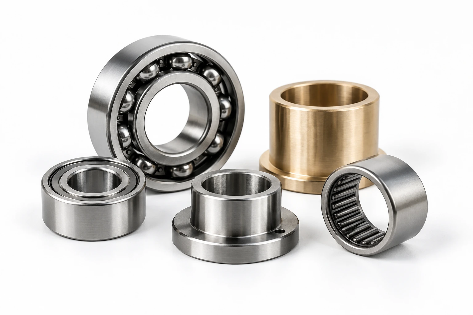
In a rolling-element bearing, this can change load distribution and increase vibration transmission into the housing. In a fluid-film bearing, it can disturb the oil film and change the dynamic forces acting on the rotor.
The most common signature is often related to 1× running speed. However, the complete vibration spectrum may also include harmonics, resonance effects, electrical orders, or bearing-frequency components. The final NVH result depends on rotor speed, bearing type, shaft stiffness, rotor mass, housing structure, and the response of the complete drive system.
Uneven Air Gap Can Add Electromagnetic Excitation
Runout at the rotor or shaft can also shift the rotor away from the magnetic centerline. This changes the air gap between rotor and stator.
A nonuniform air gap can create unbalanced magnetic pull. The electromagnetic force then adds to the mechanical excitation from the rotating shaft. In some motors, this interaction raises housing vibration or produces tonal noise at specific speed ranges.
This is why a shaft can meet a broad diameter tolerance yet still cause unacceptable NVH. Diameter controls size; runout controls how that diameter rotates relative to the functional datum axis.
Check the Correct Features and Datums
Do not measure only the shaft end. Inspect the surfaces that control the real rotor-bearing system:
- Bearing journals
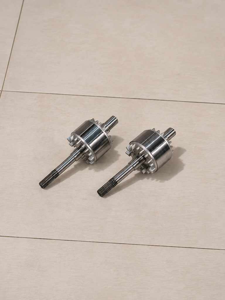
- Rotor lamination or magnet seat
- Encoder or resolver seat
- Coupling or gear interface
- Shaft shoulder faces
- Related bearing bores and housing locations
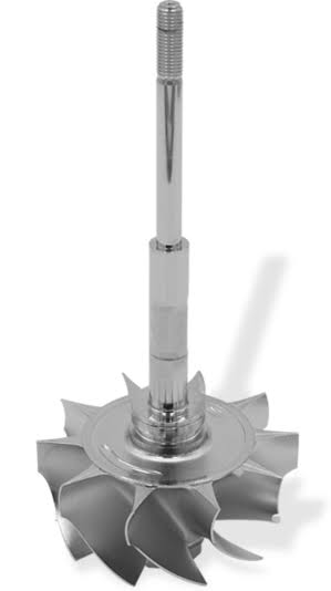
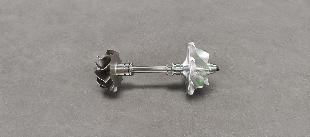
Use the functional bearing journals or specified datum axis for setup. Then record total indicated runout at multiple axial positions and angular locations. Also inspect roundness, taper, straightness, and seating condition. A bowed shaft, an eccentric rotor fit, a damaged journal, or a contaminated assembly surface can all appear as runout.
Balance Cannot Correct Every Runout Problem
Rotor balancing corrects mass distribution. It does not necessarily correct a bent shaft, eccentric journal, distorted bearing seat, or off-center rotor stack.
If runout is the root cause, adding balance mass may improve one operating condition while leaving bearing loading and air-gap variation unresolved. Diagnose geometry before changing the balance correction.
Compare vibration before and after rotor removal, shaft runout before and after assembly, and rotor position relative to the bearing journals. These comparisons separate a shaft problem from a housing, bearing, or electromagnetic issue.
Control Runout in the Manufacturing Process
Preventive control starts with stable datum selection and minimal re-clamping. Finish critical journals and rotor seats in the same setup whenever practical. Protect the shaft from handling damage after grinding or turning.
For high-volume production, link runout data with NVH test results. A trend can reveal whether the source is material straightness, chucking, press-fit eccentricity, bearing installation, or a process shift.
Conclusion
Excessive rotor shaft runout can increase mechanical vibration, bearing load, air-gap variation, and motor noise.
The effective solution is not simply to rebalance the rotor. Control the shaft, rotor, bearings, and functional datum axis as one rotating system.