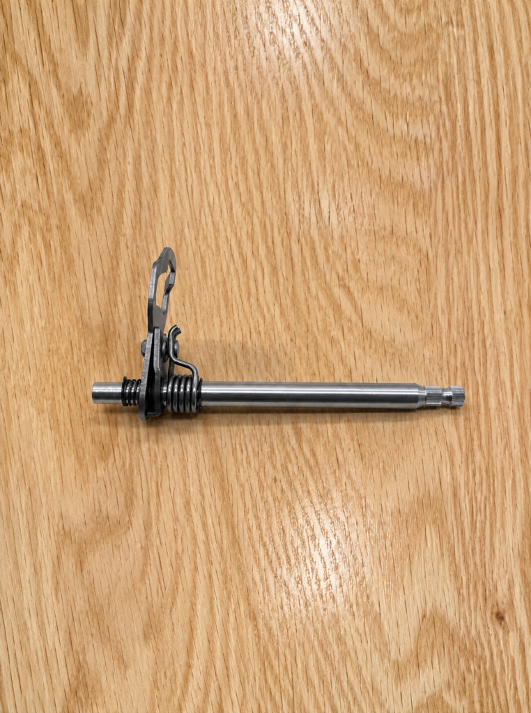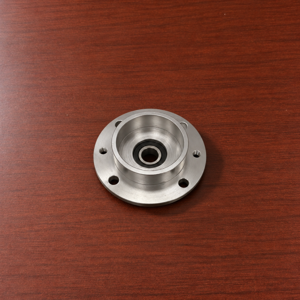
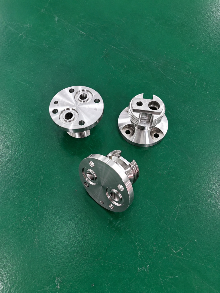
Turn-mill machining combines turning, milling, drilling and threading within one CNC platform. Instead of moving a component between a lathe and a machining center, several operations can be completed while the part remains referenced to the same spindle or fixture.
This approach is particularly useful for components that contain both rotational geometry and off-center features.
Two Different Production Routes
A conventional process may begin by turning the outer diameter and bore on a CNC lathe. The unfinished part is then removed, stored and transferred to a machining center for flats, slots and cross holes.
A turn-mill process completes these features through one coordinated program.
| Conventional production | Turn-mill production |
|---|---|
| CNC turning on the first machine | Turning in the main spindle |
| Manual unloading | Workpiece remains clamped |
| Transfer to another machine | C-axis indexes the part |
| New fixture and alignment | Driven tools mill and drill features |
| Second program and setup | Operations run in one program |
Reducing transfers does not mean that every component is completed in one physical clamping. Some parts still require a sub-spindle transfer or a second operation to reach the rear face. However, the number of separate machines and fixtures can still be reduced.
Maintaining One Machining Reference
Every time a part is reclamped, its new position must be established relative to the next machine. Small differences between setups can accumulate across bores, shoulders, slots and holes.
In a turn-mill center, the main spindle provides the rotational reference for both turning and indexed milling. Off-center holes and flats can therefore be positioned relative to the diameters machined earlier in the cycle.
A sub-spindle may collect the component directly from the main spindle. The rear face can then be turned, drilled or milled without manual unloading between operations.
Replacing Separate Milling Operations
Driven tools allow the machine to perform operations that would normally require a machining center. The C-axis controls angular position, while a Y-axis provides movement above or below the spindle centerline.
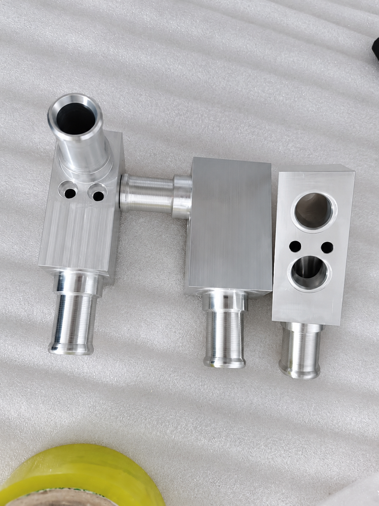
This arrangement can produce bolt circles, keyways, side holes, milled flats and radial threads. Simultaneous axis movement may also create helical or contoured features on suitable components.
Tool access and holder clearance must still be reviewed carefully because a turn-mill machine has a different working envelope from a dedicated machining center.
Reducing Work Between Operations
Fewer transfers reduce the need for intermediate fixtures, work-in-process storage and repeated coordinate setting. The operator also spends less time unloading, transporting and realigning partially machined parts.
The greatest benefit occurs when the complete operation sequence is planned before programming begins. Turning, milling and drilling should be arranged to preserve rigidity and provide access to later tools.
Turn-mill machining reduces movement between production stages by keeping related operations inside one controlled machining cycle. For suitable parts, this simplifies handling while maintaining a consistent reference between rotational and non-rotational features.