Remove Mass from the Right Region
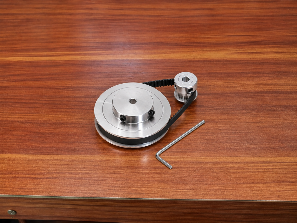
Timing pulley weight reduction holes should remove material from the web without weakening the toothed rim, hub, or connection between them.
The web often carries less local contact load than the teeth and shaft interface, making it the usual location for weight reduction. However, the remaining material must still transfer torque from the hub to the rim without excessive deflection.
Removing material close to the tooth root or shaft bore can reduce stiffness where it is most needed.
Start with Rotational Symmetry
A balanced hole pattern should repeat evenly around the rotational axis. Equal hole diameters, radial positions, and angular spacing help keep the center of mass near the shaft axis.
| Design Condition | Possible Result |
|---|---|
| Unequal hole spacing | Static imbalance |
| Different hole diameters | Uneven mass distribution |
| Holes at different radii | Increased imbalance effect |
| Hole close to the toothed rim | Reduced rim stiffness |
| Hole close to the hub | Weak torque-transfer section |
| Sharp hole transition | Local stress concentration |
| Pattern interrupted by a keyway | Asymmetric mass distribution |
A visually symmetric pattern may still be unbalanced if the keyway, set-screw hole, flange, or hub shape removes mass from only one side.
Protect the Load Path
Torque travels from the shaft through the hub and web before reaching the toothed rim. The hole pattern should leave continuous material paths between these regions.
Large openings may create narrow spokes that bend under belt tension. Several smaller, evenly arranged holes may provide better stiffness than a few large cutouts, although they can increase machining time.
Generous internal radii reduce stress concentration around milled pockets. Drilled circular holes naturally avoid sharp internal corners and are usually easier to manufacture consistently.
Account for Existing Asymmetry
Keyways, clamping slots, set-screw holes, and timing marks affect the pulley’s mass distribution before weight reduction begins.
The reduction pattern may need a controlled offset or a smaller hole near the lighter side. This compensation should be based on mass-property analysis or balancing results rather than visual judgment.
If two flanges are attached separately, their thickness, runout, and joining method should also be included in the balance review.
Maintain Machining Consistency
All reduction holes should be produced from a reliable central datum. Their diameter and radial position must remain consistent around the pulley.
Burrs and uneven chamfers can introduce small mass differences, especially on lightweight or high-speed pulleys. Machining both sides consistently also prevents local thickness variation in the web.
Surface treatments and inserted fasteners should be included in the final assembled condition.
Verify the Finished Pulley
CAD mass-property analysis can identify an obvious center-of-mass offset, but the completed pulley should still be inspected for bore runout, tooth concentricity, flange runout, and balance.
The required balance method depends on pulley diameter, mass, rotational speed, and application sensitivity. High-speed or precision systems may require dynamic balancing after all machining and assembly operations are complete.
Effective timing pulley weight reduction holes use a repeatable symmetric pattern while preserving the structural path between the hub and toothed rim. Final verification confirms that manufacturing variation has not introduced harmful imbalance.