
Define Which Gap Matters
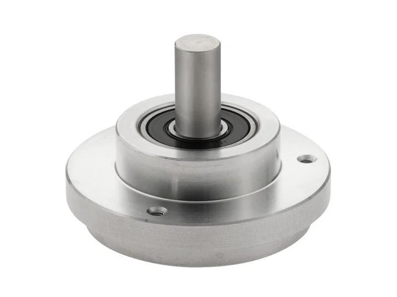
Encoder mounting flange axial clearance should be defined from the functional sensing position rather than from the visible exterior of the encoder.
Depending on the encoder type, the critical distance may be the gap between a magnetic sensor and target, an optical disc and read head, or a rotating hub and stationary housing. The acceptable value should come from the encoder manufacturer’s installation requirements.
The flange must place the stationary and rotating components within this permitted range after assembly.
Trace the Axial Dimension Chain
The final gap is affected by every feature between the shaft reference and the encoder mounting surface.
| Tolerance Contributor | Possible Effect |
|---|---|
| Shaft shoulder position | Moves the encoder rotor axially |
| Flange thickness | Changes the encoder housing position |
| Mounting-face flatness | Tilts the encoder and creates an uneven gap |
| Pilot depth | Prevents the flange from seating completely |
| Bearing axial play | Allows the shaft to move during operation |
| Coupling position | Pushes or pulls the encoder shaft |
| Gasket or coating thickness | Shifts the mounted encoder |
| Spacer or shim thickness | Directly changes the working clearance |
A tolerance stack should be calculated using the maximum and minimum permitted dimensions rather than only the nominal CAD model.
Use Functional Locating Surfaces
The encoder mounting face should reference the same axis and axial datum used to locate the shaft or bearing system. A machined shoulder can establish the axial position, while a pilot diameter controls radial location.
Mounting screws should clamp the encoder against the locating face. They should not be used to pull an incorrectly positioned encoder into alignment.
Burrs, paint, anodizing buildup, cables, and trapped debris must not prevent full contact between the flange and encoder.
Separate Location from Adjustment
If production variation cannot be controlled entirely through machining, provide a deliberate adjustment method.
Precision shims or a controlled spacer can set the encoder position without modifying the flange. Slotted mounting holes may permit adjustment, but they should not allow the encoder to move after tightening.
The adjustment direction must be accessible during assembly, and the final position should be measurable before the mechanism is closed.
Avoid Axial Loading Through the Coupling
A rigid connection between the drive shaft and encoder shaft can transmit bearing movement, thermal expansion, and assembly error directly into the encoder.
A suitable flexible coupling should accommodate the expected axial and angular misalignment without applying excessive thrust. The coupling must be installed at its specified working length rather than fully compressed or stretched.
For hollow-shaft encoders, the shaft stop, clamp position, and anti-rotation feature must follow the manufacturer’s arrangement.
Verify the Installed Condition
Measure the axial position after the bearings, flange, coupling, coating, gasket, and encoder have been assembled. Rotate the shaft and confirm that the clearance remains stable through a complete revolution.
The design should also be checked at operating temperature because the shaft, housing, and flange may expand by different amounts.
Reliable encoder mounting flange axial clearance comes from a clear functional datum, a controlled tolerance chain, suitable adjustment features, and verification in the completed assembly.