Crowding Begins Around the Interfaces
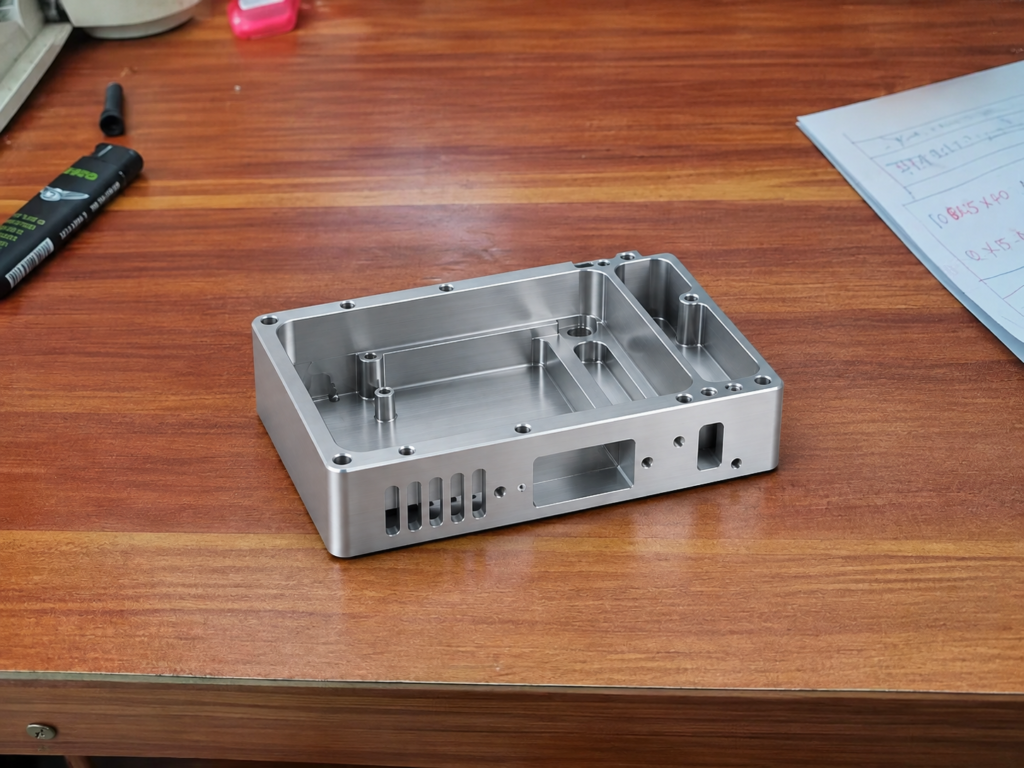
Dense interface area design becomes difficult when connectors, ports, switches, fasteners, and labels must fit within a limited panel area.
Each interface may appear acceptable when checked individually. Problems emerge after openings, counterbores, mounting holes, internal reliefs, and corner radii are combined. The remaining walls may become too thin, while nearby features block the cutter or tool holder.
The layout must therefore be evaluated as one machining region rather than as separate holes.
Check the Remaining Material
The visible spacing between two openings does not always represent the true wall thickness. Counterbores, internal pockets, chamfers, and connector bodies may extend beyond the front profile.
| Design Condition | Possible Problem |
|---|---|
| Openings placed too closely | Weak material bridge between interfaces |
| Counterbores overlap internally | Breakthrough or reduced wall strength |
| Port located near an enclosure edge | Distortion during machining or assembly |
| Deep recess beside a tall wall | Limited cutter and holder clearance |
| Fastener hole beside a large opening | Cracking or local deformation |
| Different interface depths | Additional tools and machining setups |
Section views should be used to inspect the narrowest remaining material through the full panel thickness.
Reserve Space for the Cutter
A feature may be reachable in the CAD model but still be difficult to machine. The cutting edge, tool shank, holder, spindle nose, and required approach direction all need clearance.

Small cutters can enter narrow spaces, but they are less rigid and may require slower feeds and multiple passes. Long tools increase vibration and reduce dimensional stability.
Increasing the distance between features can permit a shorter, larger-diameter cutter and make the operation more reliable.
Simplify the Opening Layout
Closely spaced interfaces should use consistent opening depths, corner radii, and fastener sizes whenever function allows. Standardized features reduce tool changes and make the machining path easier to plan.
Moving mounting screws outside the most crowded region may preserve stronger walls. Connector flanges can sometimes share a supporting surface, while local bosses or thicker panel regions can reinforce areas weakened by large openings.
The external appearance should not be finalized before the internal connector bodies and machining clearances are checked.
Review Assembly and Service Access
Machining clearance alone is not enough. Plugs, locking clips, cable bends, screwdrivers, and technician fingers also require space.
A connector that fits the panel may still be impossible to fasten or disconnect after adjacent components are installed. Assembly order should be tested using the complete interface arrangement.
Confirm the Final Geometry
Before release, inspect the design from the front, back, and in cross-section. Check minimum wall thickness, tool approach, holder clearance, connector envelope, cable direction, and fastener access.
Effective dense interface area design balances compact packaging with adequate material and realistic machining access. Small layout changes made early can prevent fragile walls, special tooling, additional setups, and assembly interference.