The Plate Begins to Ring
Large thin base plate design may look acceptable in a static CAD model but behave very differeDesign Guidelinesntly under cutting forces, motor vibration, or repeated operating loads.
When the unsupported center begins to move, the plate can act like a diaphragm. The result may be machining chatter, noise, unstable components, loose fasteners, or inaccurate measurements.
The main issue is usually insufficient stiffness across a large unsupported span.
Read the Structural Warning Signs
| Design Condition | Likely Effect |
|---|---|
| Large unsupported center | High deflection and vibration |
| Mounting points only at corners | Center remains flexible |
| Flat edges without returns | Low bending stiffness |
| Long ribs in one direction | Weakness remains across the other axis |
| Abrupt thickness changes | Local stress concentration |
| Thin areas near dynamic loads | Vibration enters the plate directly |
The plate should be reviewed as part of the complete assembly rather than as an isolated flat component.
Shorten the Unsupported Span
Reducing the distance between supports is often more effective than increasing the thickness of the entire plate.
Additional mounting points, support pads, or contact rails can divide one large flexible area into several smaller regions. Supports should be positioned near motors, bearings, cutting loads, or other vibration sources.
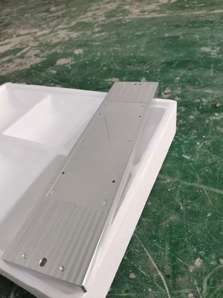
All support surfaces must remain coplanar. An uneven support can distort the plate when the fasteners are tightened.
Add Stiffness Where It Matters
Ribs increase bending stiffness without making the entire plate solid. A crossed or grid pattern can provide support in multiple directions, while ribs connected to mounting bosses create a more continuous load path.
Raised edges or downward-facing flanges can also improve stiffness significantly. Their height is often more important than adding a small amount of thickness to the flat surface.
Rib transitions should use suitable radii to avoid abrupt stress concentrations and difficult machining areas.
Keep Mass and Geometry Balanced
Removing material from one side can create uneven stiffness and residual stress. Large pockets should be arranged symmetrically where possible, with enough material left around mounting points and functional surfaces.
A very heavy local boss connected to a thin plate can also create a flexible transition. Gradual thickness changes distribute the load more effectively.
Validate the Complete Assembly
Static deflection alone does not describe vibration behavior. The plate’s natural frequencies should remain separated from expected motor speeds, cutting frequencies, and repeated operating loads.
Finite element analysis can help compare rib layouts and mounting positions. Final validation should use the real fasteners, supports, and attached equipment because these elements change the structural response.
Conclusion
A large thin base plate becomes more stable when unsupported spans are reduced and stiffness is added along clear load paths.
Well-positioned supports, multidirectional ribs, rigid edge flanges, and balanced geometry can reduce vibration without making the entire plate unnecessarily thick.