
Key Design Decisions
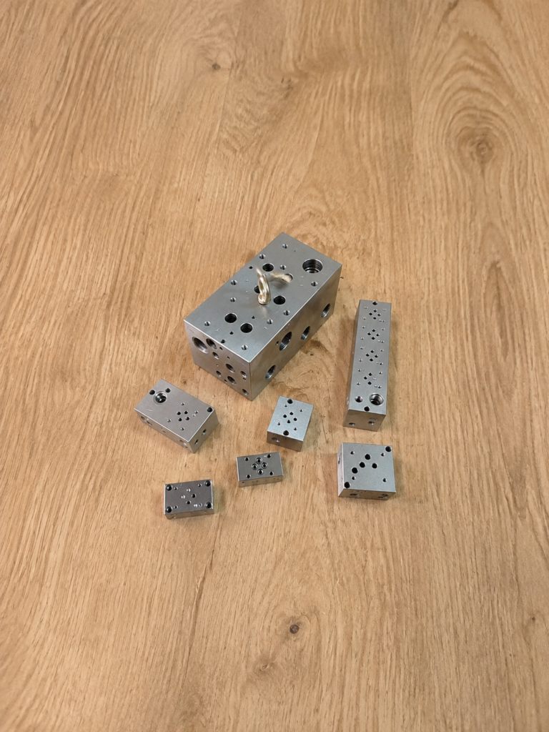
CNC threaded hole design affects part strength, assembly reliability, machining cost, and production time. A thread that is too deep, too close to an edge, or difficult to reach can increase manufacturing risk.
A practical design provides enough engagement for the expected load while leaving sufficient space for drilling, tapping, chip removal, and inspection.
Key Design Decisions
| Design Item | Recommendation |
|---|---|
| Thread type | Use a common standard |
| Thread size | Avoid unnecessarily small threads |
| Thread depth | Specify the required full thread depth |
| Blind-hole allowance | Leave space for the tap tip and chips |
| Edge distance | Maintain enough surrounding material |
| Tool access | Provide a direct approach to the hole |
| Thread tolerance | Use a standard class when possible |
| Hole entrance | Add a small assembly chamfer |
Standard thread sizes are easier to machine, inspect, and replace. Unusual sizes may require special taps and gauges, increasing cost and lead time.
Select the Thread Size and Depth
Thread size should be based on the fastener load, available wall thickness, assembly frequency, and surrounding space. Very small threads are harder to tap and may leave weak walls around the hole.

Thread engagement is the length over which the internal and external threads connect. Excessively deep threads increase machining time and the risk of chip blockage without always providing useful additional strength.
If the available depth is limited or the connection will be assembled repeatedly, a threaded insert may be more suitable than a directly tapped hole.
Allow Space in Blind Holes
A blind threaded hole does not pass through the part. Its drilled depth must therefore be greater than the required full thread depth.
The additional space accommodates the tapered end of the tap and provides room for chips. If the drilled hole ends at the same depth as the thread, complete threads may not be produced near the bottom.
The drawing should clearly distinguish between drill depth and full thread depth. When possible, a through hole is simpler because chips can exit from the opposite side.
Check Edge Distance and Tool Access
A threaded hole placed too close to an edge, pocket, or thin wall can weaken the surrounding structure. Sufficient material should remain around the thread for the expected assembly load.

The drill, tap, and tool holder must also approach the hole without interference. Deep recesses, angled surfaces, and nearby walls may block access and require additional setups.
Relocating the hole or increasing local clearance can simplify machining and reduce cost.
Specify Threads Clearly
The drawing should identify the thread standard, nominal size, pitch, tolerance class, and required full thread depth. Blind holes should also show the necessary drill depth.
Do not rely only on the appearance of threads in a 3D model. Thread geometry is often represented symbolically, so a complete thread callout is still required.
The drawing should also state whether the hole is through or blind. Positional tolerances and special inspection requirements should only be added when needed for assembly or function.
Conclusion
Reliable CNC threaded hole design requires a practical thread size, sufficient engagement, adequate blind-hole clearance, and suitable edge distance and tool access.
Clear specifications help manufacturers choose the correct drilling, tapping, and inspection methods while avoiding unnecessary cost and machining risk.