Begin with the Optical Relationship
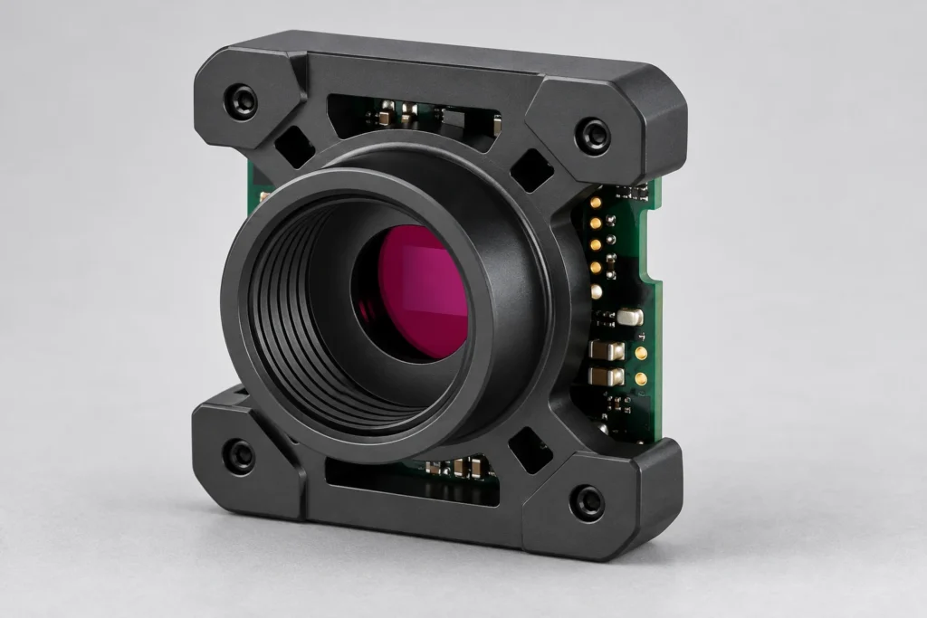
Camera housing sensor and lens alignment depends on two primary relationships: the lens bore must follow the intended optical axis, and the sensor plane must remain perpendicular to that axis.
A small angular error at the sensor can produce uneven focus across the image. A lateral offset between the lens and sensor may shift the image field or reduce usable image quality.
The housing must therefore control position and orientation, not only the individual dimensions of the lens hole and sensor mounting surface.
Establish a Common Datum System
The lens bore and sensor mounting plane should reference the same functional datums. Using unrelated exterior surfaces can introduce error through multiple setups and tolerance accumulation.
| Feature | Primary Requirement |
|---|---|
| Lens bore | Position and axis direction |
| Sensor mounting plane | Flatness and perpendicularity |
| PCB locating features | Position relative to the optical axis |
| Fastener holes | Clearance without shifting the PCB |
| Housing reference surfaces | Repeatable machining and assembly location |
A practical datum system typically begins with the sensor mounting plane or another stable internal surface. Secondary datums then control horizontal and vertical positioning.
Cosmetic exterior faces should not be used as critical alignment references unless they are machined and controlled for that purpose.
Control the Machining Sequence
Where possible, machine the lens bore and sensor reference surface in the same setup. This reduces errors caused by reclamping and datum transfer.
If multiple setups are unavoidable, use accurately machined locating features to recover the original coordinate system. The workholding method must support the housing without distorting its walls or sensor mounting area.
The lens thread alone should not define optical alignment. Thread clearance can allow the lens barrel to shift or tilt. A precision pilot diameter or seating shoulder provides a more reliable locating feature.
Locate the Sensor Assembly
Fasteners secure the PCB but should not be expected to locate it precisely. Clearance around screw holes allows movement during assembly.
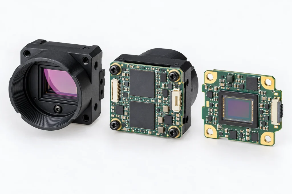
Use locating pins, fitted edges, or dedicated reference bosses to position the sensor board. The locating features should control the PCB without creating an over-constrained assembly.
The sensor package position on the PCB also has its own tolerance. Housing accuracy cannot compensate for variation between the sensor die, package, and board. The complete tolerance chain must include both machined and electronic components.
Allow Final Adjustment When Necessary
High-resolution or long-focal-length systems may require active alignment. In this process, the sensor or lens position is adjusted while image performance is measured.
The housing can support this process through controlled adjustment slots, shim locations, or accessible locking features. After alignment, the assembly must remain stable under vibration and temperature changes.
Conclusion
Reliable camera alignment begins with shared functional datums. Machining the lens bore and sensor reference surface in one setup, using dedicated locating features, and evaluating the complete assembly tolerance chain reduce optical-axis error.
For demanding imaging systems, CNC accuracy should establish a stable mechanical reference while final optical alignment confirms actual image performance.