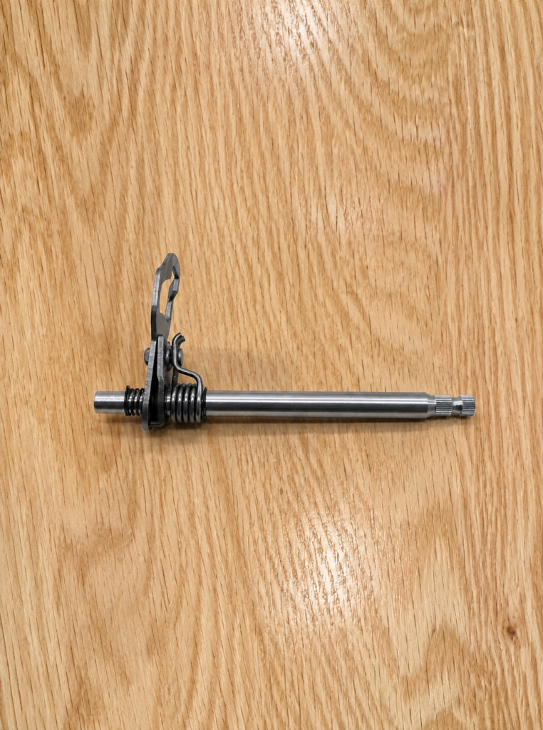
Automotive shift shaft CNC machining produces the rotating or sliding member that transfers driver input to the transmission selector mechanism. The shaft may combine bearing diameters, shoulders, splines, lever-mounting sections and transverse holes within a narrow component.
Every feature must share a controlled axial and angular relationship. An incorrectly oriented cross hole or spline can change the installed position of the selector lever.
Turn the Shaft from One Axis
The operation begins with bar stock held in the main spindle. Facing establishes the first end before rough turning forms the main shaft profile.
Bearing sections, reduced diameters and shoulders are turned in sequence. Enough material is retained around slender areas during roughing so the shaft remains supported under cutting pressure.
A finishing pass completes the diameters that rotate or slide inside the transmission housing. Chamfers are added where the shaft must pass through seals, bushings or assembly openings.
Prepare the Spline Section
The spline transfers rotary movement between the shift shaft and a connected lever, arm or coupling. Its blank diameter is turned before the individual teeth are produced.
External splines may be machined by hobbing, form milling or spline rolling. On a turn-mill center, a form cutter can machine one tooth space before the spindle indexes to the next angular position.

The spline must remain concentric with the finished bearing diameters. Its starting angle may also be controlled so the external lever reaches the correct neutral position after assembly.
A relief beside the spline provides cutter clearance and prevents the tooth form from ending against an unfinished shoulder.
Index and Drill the Cross Hole
A transverse hole may carry a spring pin, retaining pin or connection for a selector component. The hole is positioned from a finished shoulder rather than from the unfinished bar end.
The spindle stops at the programmed angle while a live drill approaches the shaft radially. Spot drilling helps prevent movement on the curved outer surface before the hole is drilled through.
Feed is reduced near breakthrough to limit the burr on the opposite side. When the design requires a fitted pin, reaming follows drilling to complete the hole size.
Its angular position is referenced to the spline so the connected parts remain correctly oriented.
Add Grooves and Lever Features
Some shift shafts include retaining-ring grooves, detent grooves or milled flats. Grooves are turned while the shaft remains aligned with the spindle axis.
A lever-mounting flat is milled after the spindle indexes from the same reference used for the cross hole. This keeps the flat, spline and pin location connected within one machining setup.
Complete the Second End
A sub-spindle can grip a finished diameter before the shaft is cut from the bar. The rear face is then machined to final length, followed by any remaining thread, chamfer or end slot.
Burrs are removed from the cross hole and spline edges without rounding the functional tooth profile. Reliable automotive shift shaft CNC machining keeps the stepped diameters concentric while maintaining the required angular relationship between the spline, flat and transverse hole.