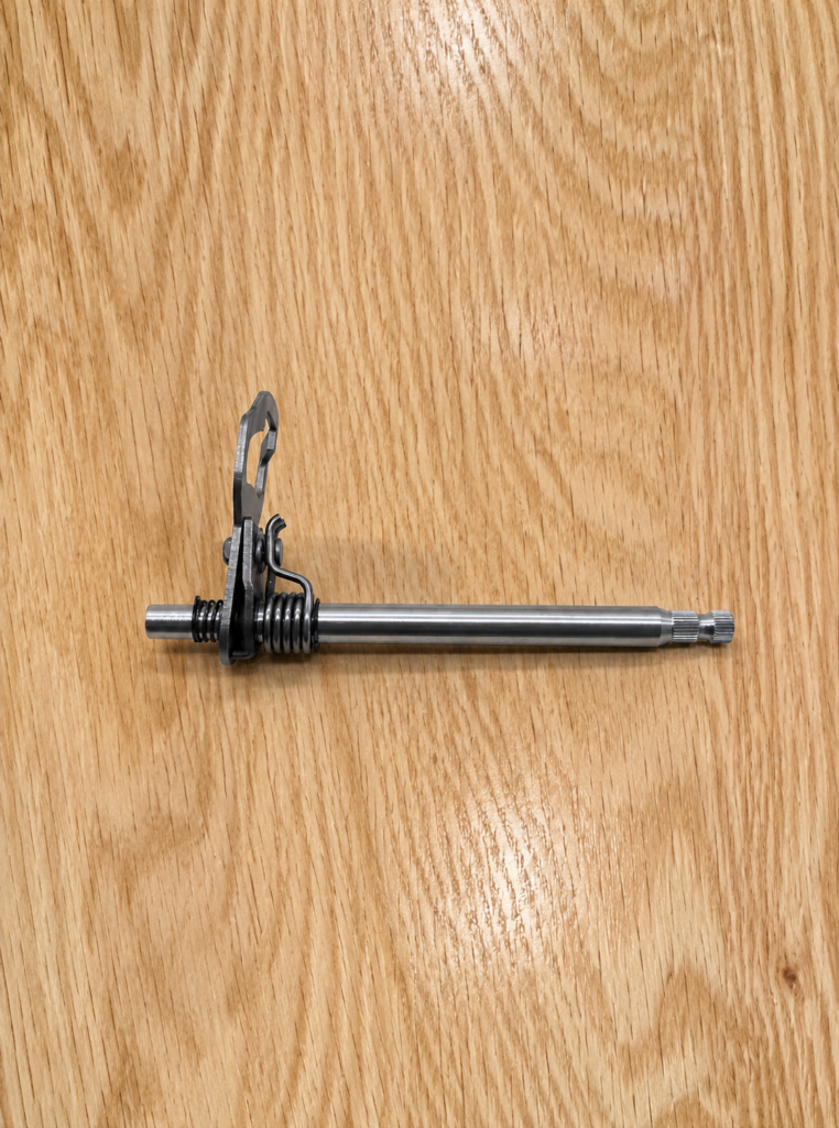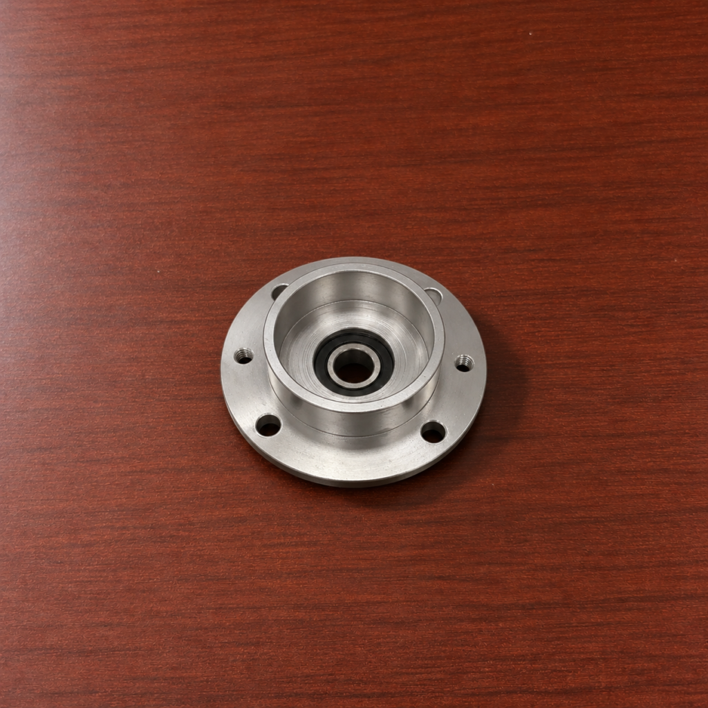

Robot arm cable mount CNC machining produces brackets that guide cables, hoses or protective conduits along a moving arm. The part may include a curved mounting surface, cable groove, split-clamp area and holes entering from several directions.
The curved seat must match the arm or cable path, while the mounting holes must remain correctly positioned around that surface.
Establish the Flat References
Machining begins by facing the blank to create a stable fixture surface. Two perpendicular sides are then milled to establish the part origin.
Mounting tabs and thicker base areas are rough machined while the blank still provides strong support. These areas will later carry the screw holes and absorb the clamping force during assembly.
The outer profile is left with a small finishing allowance until the internal cable features are complete.
Rough the Curved Seat
The main curved surface may wrap around a cylindrical robot-arm section or support a cable bundle. A ball-nose or bull-nose cutter removes the material in successive passes.
For a simple cylindrical seat, a three-axis tool path can step across the arc. A five-axis machine can tilt the cutter as it follows a deeper wraparound surface, improving access near the sidewalls.
Roughing leaves a uniform allowance over the complete curve. This gives the finishing tool a consistent amount of material to remove.
Finish the Cable Groove
The cable-contact groove is machined after the larger seat has been established. Its path may be straight, angled or gently curved across the bracket.
A smaller cutter follows the groove centerline and finishes the bottom radius. Sudden changes in tool direction are avoided because they can leave marks on the cable-contact surface.
If the part holds several cables, parallel grooves are machined from the same coordinate reference. Their spacing must remain consistent with the cover plate or mating clamp.
Drill the Mounting Holes
Hole locations are calculated from the finished base and side references rather than from the unfinished curved edge. Spot drilling establishes each position before the holes are drilled.
Through-holes may receive counterbores for recessed screw heads. Threaded holes are drilled to the minor diameter before tapping or thread milling.
Some mounts require holes on both sides of the curved seat. The part can be indexed on a fourth axis or repositioned in a second fixture using the previously machined faces for location.
Separate a Split Clamp
A two-piece cable mount may be machined as matched upper and lower blocks. The contact groove and locating holes are produced so the halves align when assembled.

Another method begins with one solid component. After the main bore or curved passage is machined, the part is separated along a programmed split line and the new faces are finished.
Dowel holes or locating shoulders prevent the clamp halves from shifting when the fasteners are tightened.
Complete the Accessible Edges
The bracket is repositioned for remaining side holes, end chamfers and contour finishing. Clamping avoids the completed cable groove so the contact surface is not marked.
Burrs around holes and curved edges are removed without creating sharp transitions that could contact the cable. Effective robot arm cable mount CNC machining keeps the curved seat, guiding groove and mounting-hole pattern tied to the same locating references.