
Start at the External Interface
PCB mounting boss design should begin with the components that must align with the enclosure, not with an arbitrary boss height.
A USB connector, display, button, or indicator may need to match an opening in the housing. Once this functional position is fixed, the PCB seating plane and boss height can be calculated.
This approach prevents the board from fitting mechanically while its external components remain misaligned.
Build the Height Stack
| Stack Element | Design Consideration |
|---|---|
| Enclosure reference surface | Establish a stable dimensional datum |
| Boss height | Controls the PCB seating plane |
| PCB thickness | Affects connector and component height |
| Underside components | Require clearance from the enclosure |
| Solder joints and leads | Must not contact the housing |
| Washer or spacer | Changes the final board position |
| Gasket or display interface | May introduce compression variation |
The tolerance of every element should be included. A correct nominal dimension may still fail when all variations accumulate in the same direction.
Position Bosses From PCB Datums
Boss centers should match the mounting-hole coordinates on the PCB drawing. Avoid positioning each boss from unrelated enclosure edges because this can create unnecessary tolerance accumulation.
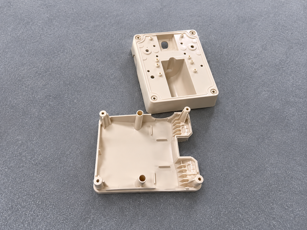
One mounting hole may establish the primary location, while other holes provide clearance for manufacturing variation. Using several tightly fitted holes can over-constrain the board and make assembly difficult.
The screw should clamp the PCB without forcing it sideways.
Support High-Load Areas
Bosses should be placed near connectors, switches, large heat sinks, transformers, or other components that experience insertion force or vibration.
A large unsupported PCB area may flex during connector use. Adding a support point can reduce movement, but it must not contact solder joints, traces, or sensitive components.
Boss quantity should be based on board size and load distribution rather than symmetry alone.
Check Assembly Access
The screwdriver must reach each fastener without interference from enclosure walls or tall PCB components. Screw heads and washers also need enough clearance from nearby electrical features.
Metal enclosures require attention to electrical isolation. Suitable spacing, insulating hardware, or dedicated grounding points may be necessary according to the product design.
Verify With the Actual Board
Before production, compare the enclosure model with the released PCB data, including component heights and keepout zones.
A physical assembly check should confirm connector alignment, underside clearance, screw access, and board flatness. Prototype boards are especially useful when connectors or displays must match tight enclosure openings.
Conclusion
Reliable PCB mounting boss design starts from the required board position and external component alignment.
A controlled height stack, datum-based hole locations, suitable support points, and adequate assembly clearance help the PCB fit without stress or misalignment.