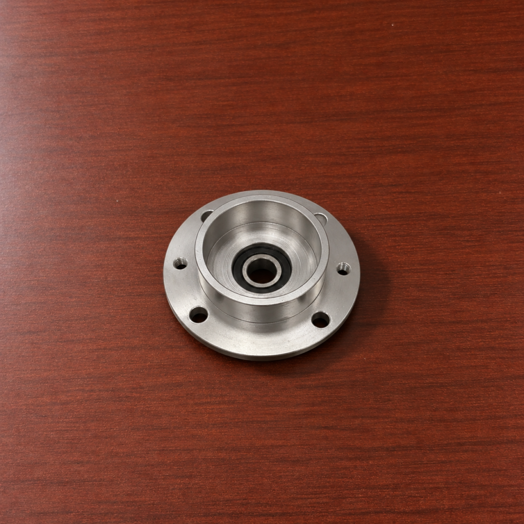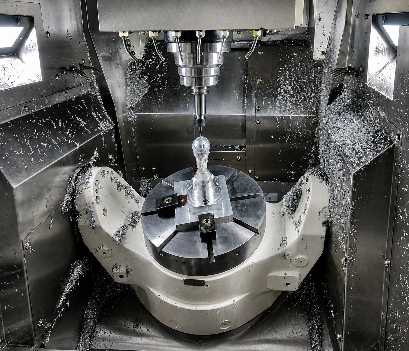

Robot wrist connector machining produces the mechanical interface between a robot wrist and its downstream joint or end-effector assembly. The component may contain a central bore, cable passages, bolt circles and angled mounting surfaces within a compact structure.
These features are located on several sides but must remain connected to the same rotational and assembly references. Five-axis CNC machining reduces repeated repositioning while providing access to restricted areas.
Begin with the Main Interface
Machining starts by establishing the primary mounting face and central locating bore. These features create the reference for the remaining operations.
The main face may include a circular locating step, bolt pattern and recessed mounting area. Machining them during the same setup helps maintain their relationship to the component centerline.
Enough stock is retained around thin walls and external arms until the internal cavity has been roughed. This gives the workpiece more support during heavy material removal.
Rotate the Part, Not the Fixture
After the main interface is established, the rotary axes position the workpiece for side features. The cutter can approach angled faces, radial holes and cable openings without removing the component from its fixture.
Indexed 3+2-axis operations are suitable for flat faces and holes at fixed angles. Simultaneous five-axis motion is more useful for curved transitions or surfaces whose tool angle must change continuously.
Reducing manual setups also limits the accumulation of positioning differences between opposite faces.
Machine the Internal Access Features
Robot wrist connectors often contain an internal opening for cables, fasteners or transmission components. This area may include deep walls and restricted corners.
Short, rigid cutters are used while the cavity remains open. Longer tools are introduced only when the required depth cannot be reached otherwise. Adaptive roughing maintains controlled cutter engagement while progressively opening the internal space.
Side holes that connect with the cavity are drilled after sufficient material has been removed. Feed may be reduced during breakthrough to limit internal burr formation.
Control Tool Orientation Around the Connector
The spindle, holder and fixture must remain clear as the machine rotates the workpiece. Toolpath simulation is therefore required before machining begins.
Tilting the tool can shorten the effective reach and improve access to angled surfaces. However, unnecessary rotary movement may reduce feed stability, so the tool axis should change smoothly between cutting regions.

For curved external transitions, ball-end or tapered tools can follow the surface while the rotary axes maintain a suitable contact position.
Complete the Assembly Features
Threaded holes, locating features and mounting slots are normally completed after the main cavity and interfaces have stabilized. Accessible edges and internal openings are then deburred and cleaned.
The bore, mounting faces, bolt patterns and angled connections are checked against the customer’s drawing before delivery.
Reliable robot wrist connector machining depends on a stable primary reference, planned tool access and a five-axis sequence that preserves the relationship between every assembly interface.