Begin at the Crack
Press-fit part cracking after assembly usually indicates that the surrounding structure could not safely withstand the stress created during insertion.
The engineer first examines where the crack started. A split running outward from the bore often points to excessive interference or insufficient wall thickness. Damage concentrated at the bore entrance may indicate poor alignment or an inadequate lead-in feature.
The crack pattern helps determine whether the problem began with the fit, the geometry, or the assembly method.
Read the Failure Pattern
| Observed Damage | Likely Design Cause |
|---|---|
| Radial crack from the bore | Excessive interference |
| Split through a thin boss | Insufficient surrounding material |
| Crack at a sharp corner | Stress concentration |
| Damage at the bore entrance | Poor lead-in or misalignment |
| Cracking near an edge | Inadequate edge distance |
| Failure after temperature change | Thermal expansion mismatch |
Several causes may act together. A moderate interference can still produce failure if the bore is close to an edge or connected to a sharp internal corner.
Check the Interference Range
The designer must evaluate the smallest permitted hole against the largest permitted inserted part. This worst-case combination produces the highest interference and assembly stress.
Nominal dimensions alone are not sufficient. The complete tolerance range, roundness, surface condition, and assembly temperature influence the actual force.

Increasing interference does not always improve joint reliability. Once sufficient holding force is achieved, additional interference mainly increases assembly load and hoop stress.
Review the Surrounding Geometry
The material around the bore must be thick enough to distribute the radial load. Thin bosses, nearby slots, cross-holes, and external edges reduce structural support.
Sharp transitions can concentrate stress and provide a starting point for cracks. Smooth radii between the boss and surrounding structure distribute the load more effectively.
The bore should also remain far enough from external edges and other features. If space is limited, a larger boss or alternative retention method may be required.
Control the Entry and Alignment
A lead-in chamfer helps center the inserted component before full contact begins. Without it, the part may enter at an angle and apply high local pressure to one side of the bore.
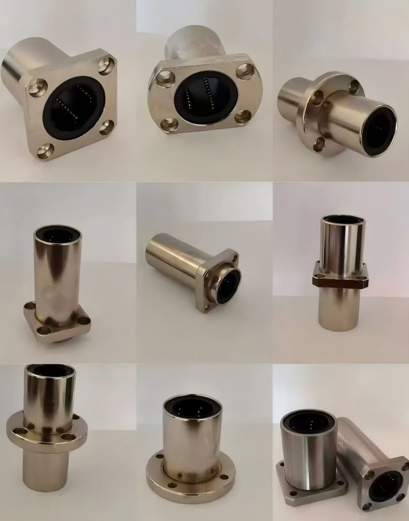
The press tool should apply force along the bore axis. The design must provide stable support beneath the receiving part so that the surrounding structure does not bend during insertion.
If alignment is difficult to control, a longer pilot section can guide the components before the interference surfaces engage.
Consider Service Conditions
Assembly is not always the final loading event. Temperature changes can increase interference when the inserted part and housing expand at different rates.
Vibration, repeated loading, and environmental exposure may also cause a small assembly crack to grow over time. The fit should therefore be evaluated under actual service conditions, not only immediately after pressing.
Conclusion
Press-fit cracking is rarely caused by one dimension alone. Excessive interference, thin surrounding walls, sharp geometry, limited edge distance, and poor insertion alignment often combine to produce failure.
Reviewing worst-case tolerances, bore support, lead-in geometry, assembly direction, and operating temperature can prevent cracking before production begins.