Silver plating for RF components is mainly used to reduce conductor loss at the surface where high-frequency current flows. Instead of manufacturing the entire component from silver, engineers apply a controlled silver layer to a stronger and less expensive substrate such as copper, brass, or aluminum.
Its value becomes clearer by following an RF signal through the component.
The Signal Moves to the Surface
At direct current, electrical current uses the conductor’s full cross-section. As frequency increases, current becomes concentrated near the outer surface—a phenomenon known as the skin effect.
This makes surface conductivity increasingly important in waveguides, filters, resonant cavities, coaxial components, connectors, and antenna hardware. A base material may provide sufficient mechanical strength, while the plated surface determines much of the RF loss.
Silver has very high electrical conductivity. When the coating is sufficiently thick and continuous relative to the operating skin depth, it can reduce surface resistance and insertion loss without requiring a solid-silver component.
The Signal Crosses a Joint
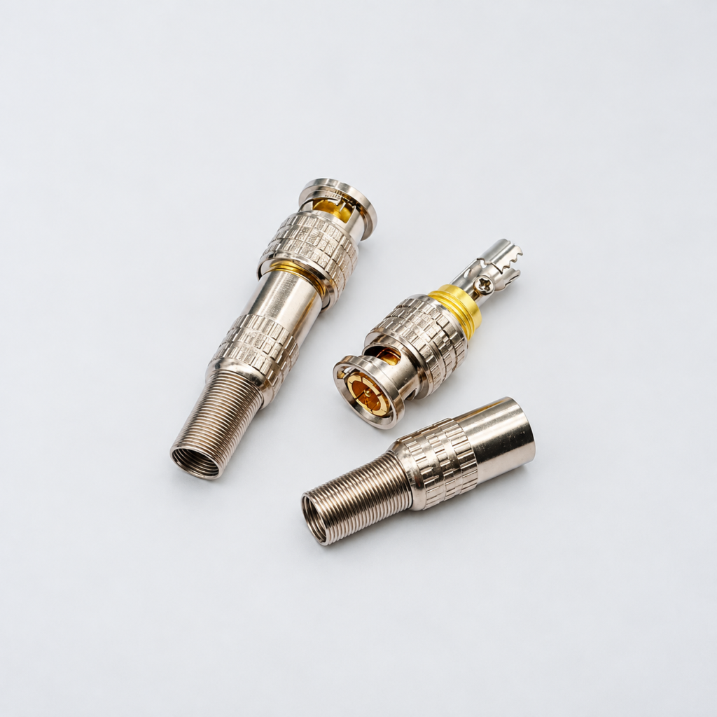
RF systems contain flanges, threaded connections, spring contacts, covers, and connector interfaces. At these locations, current must pass through small real contact areas rather than the entire visible surface.
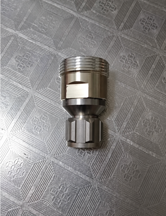
Silver is relatively soft and can conform to microscopic surface irregularities under contact pressure. This helps create a larger conductive contact area and reduce interface resistance. It is particularly useful where components must also carry high current or dissipate heat.
The same softness creates a limitation. Repeated mating, sliding, or excessive contact pressure can wear the deposit. Hard-silver formulations or suitable contact lubricants may be considered for moving interfaces, but their conductivity and RF performance should be verified for the application.
The Signal Enters a Cavity
Internal corners, deep holes, blind passages, and narrow waveguide channels are difficult to plate uniformly. Thin areas, pores, or rough deposits can increase local loss and create inconsistent performance.
Surface roughness also matters because the RF current follows the actual surface profile. A rough substrate remains rough after a thin coating, increasing the effective current path. Machining, polishing, deburring, and cleaning should therefore be completed before plating.
The coating specification should define silver purity, minimum local thickness, adhesion, porosity, surface finish, and coverage of functional areas. Thickness should be based on frequency range, expected wear, and manufacturing variation rather than a general decorative-plating value.
The Plating Stack Supports the Silver
Silver cannot always be deposited directly onto the base material. Copper and brass may use an underplate to control diffusion and improve adhesion. Aluminum requires specialized pretreatment—often involving zincate and an intermediate metal layer—because its natural oxide prevents reliable direct plating.
Nickel is commonly used as an engineering underplate, but it should be evaluated carefully in low-loss RF current paths. Its electrical and magnetic properties may increase RF loss if the silver layer is too thin or becomes worn.
The complete plating stack must therefore be designed as part of the electrical component, not merely as corrosion protection.
The Surface Meets the Environment
Silver reacts with sulfur-containing pollutants and can form a dark tarnish film. Tarnishing does not always make an RF component unusable, but it may increase contact resistance at joints and create inconsistent performance in sensitive interfaces.
Packaging, low-sulfur storage materials, environmental sealing, and approved anti-tarnish treatments can slow discoloration. Any top treatment must be thin, electrically suitable, and validated at the intended frequency. An insulating clear coat should not be applied to RF contact areas without testing.
Humidity combined with electrical bias can also promote silver migration across insulating surfaces. Plating boundaries and spacing must be controlled around dielectric materials and closely spaced conductors.
Verify the Finished RF Part
Inspection should include thickness measurement, adhesion testing, porosity evaluation, visual coverage, and surface-roughness checks. RF validation should measure insertion loss, return loss, contact stability, and power performance after thermal cycling, humidity exposure, and representative mating cycles.
Complex waveguides or cavities should be tested as finished components because coupon conductivity alone cannot reveal thin internal areas, poor joints, or dimensional changes caused by plating.
Conclusion
Silver plating improves RF components by placing a highly conductive surface exactly where high-frequency current flows. Its effectiveness depends on adequate thickness, low roughness, reliable underplating, complete coverage, and control of tarnish and wear. When these factors are managed correctly, silver provides lower RF loss without the cost or mechanical limitations of a solid-silver part.