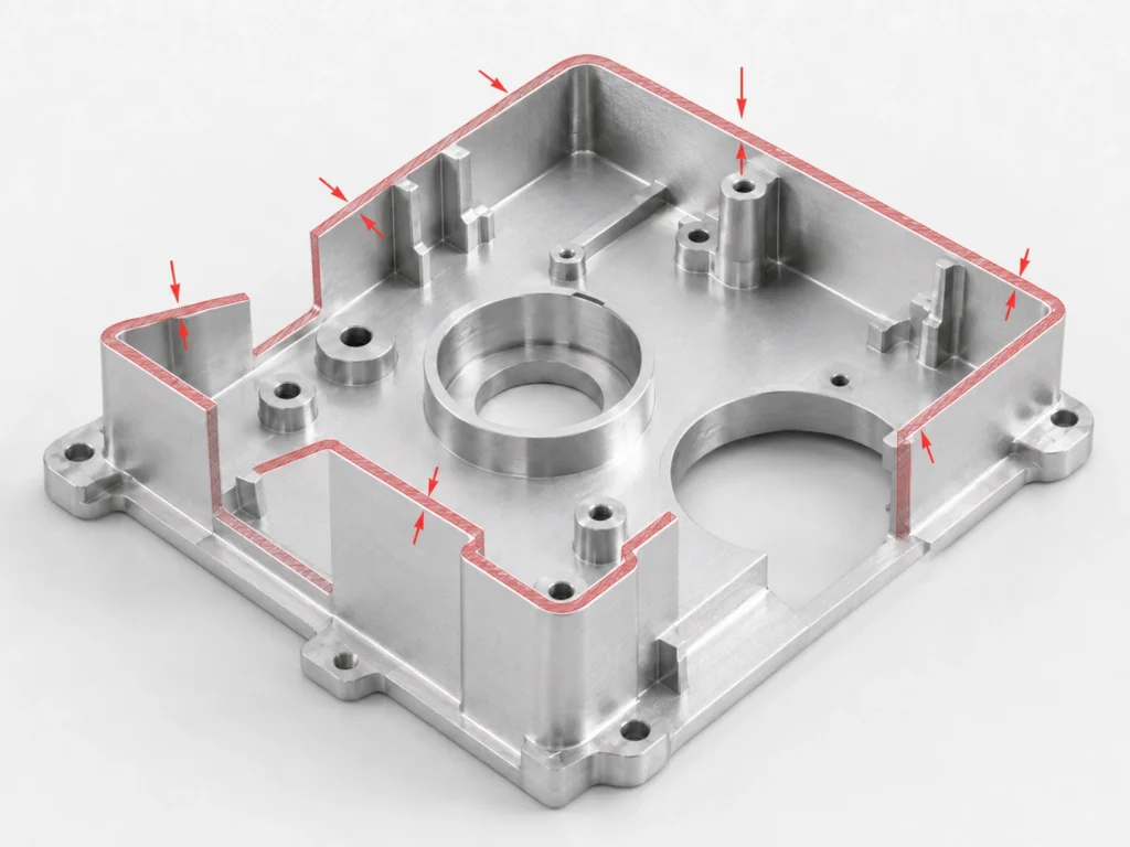
CNC Machining Wall Thickness Guidelines
Practical wall thickness guidelines for CNC machined parts to improve rigidity, dimensional stability, and manufacturability while reducing deformation risk.
Get a Quote
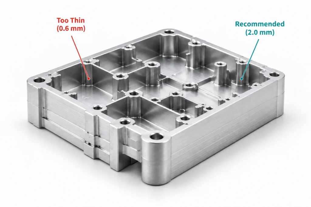
CNC machined aluminum enclosure showing thin and recommended wall thickness
WALL THICKNESS REFERENCE

Typical CNC Wall Thickness Guidelines by Material

Use these values as general starting points. Final wall thickness should be evaluated based on material, geometry, wall height, tolerances, and machining conditions.
Material
Typical Minimum
Recommended Range
Design Notes
Aluminum 6061 / 7075
1.0 mm
1.5–5.0 mm
Good rigidity and machinability
Stainless Steel 304 / 316
1.5 mm
2.0–6.0 mm
Higher cutting forces may require greater wall rigidity
Carbon & Alloy Steel
1.5 mm
2.0–6.0 mm
Greater rigidity helps maintain tighter tolerances
Brass / Copper
0.8 mm
1.0–4.0 mm
Good machinability for many part geometries
Engineering Plastics
0.8 mm
1.0–3.0 mm
Thin walls may flex, deform, or move during machining
Titanium (Ti-6Al-4V)
2.0 mm
2.5–8.0 mm
Requires greater rigidity and controlled machining parameters
For wall thicknesses below these guidelines, send us your drawing or CAD model for an engineering review.
THIN-WALL MACHINING

Thin-Wall Machining Considerations

Cutting Forces
Excessive cutting forces can deflect thin walls and affect dimensional accuracy.
Clamping & Support
Inadequate fixturing can distort thin sections during machining.
Vibration & Chatter
Thin sections are more susceptible to vibration and chatter, which can affect surface finish and dimensional accuracy.
Heat & Residual Stress
Heat generation and material removal can release residual stress and cause distortion.
Wall Height-to-Thickness Ratio
Tall, thin walls may require staged machining, additional support, or optimized toolpaths.
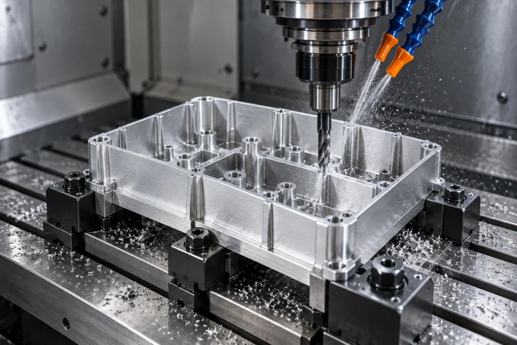
CNC milling a thin-wall aluminum enclosure with coolant and precision fixturing
DESIGN EXAMPLES

Good vs. Poor Wall Thickness Design

Compare practical wall-thickness design choices that improve rigidity, dimensional stability, and machinability.
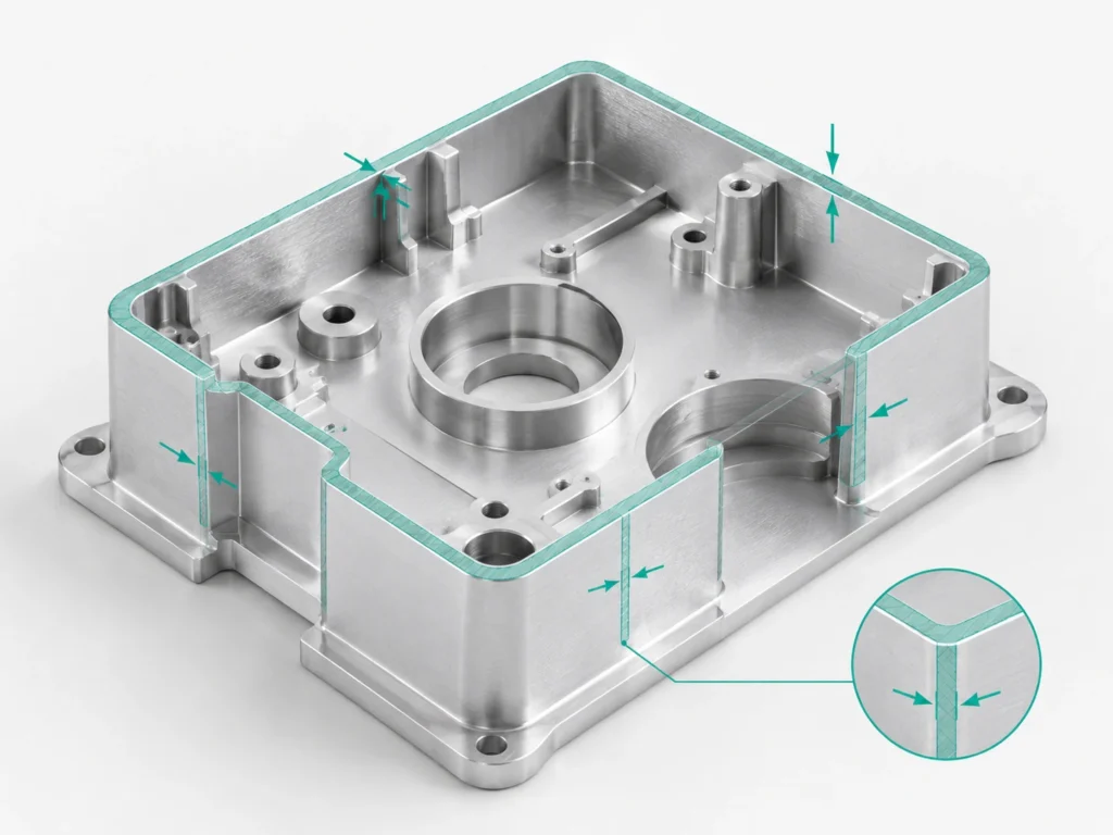
CNC machined aluminum part with uniform wall thickness design

Uniform Wall Thickness

Maintain consistent wall thickness where possible to improve rigidity and dimensional stability.
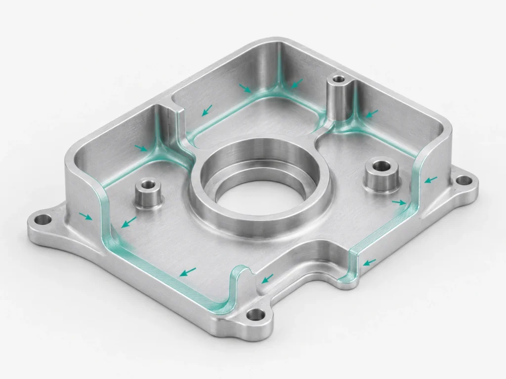
CNC machined aluminum part with smooth wall thickness transitions and radii

Smooth Thickness Transitions

Use gradual transitions and fillets between wall sections to reduce stress concentration and improve dimensional stability.
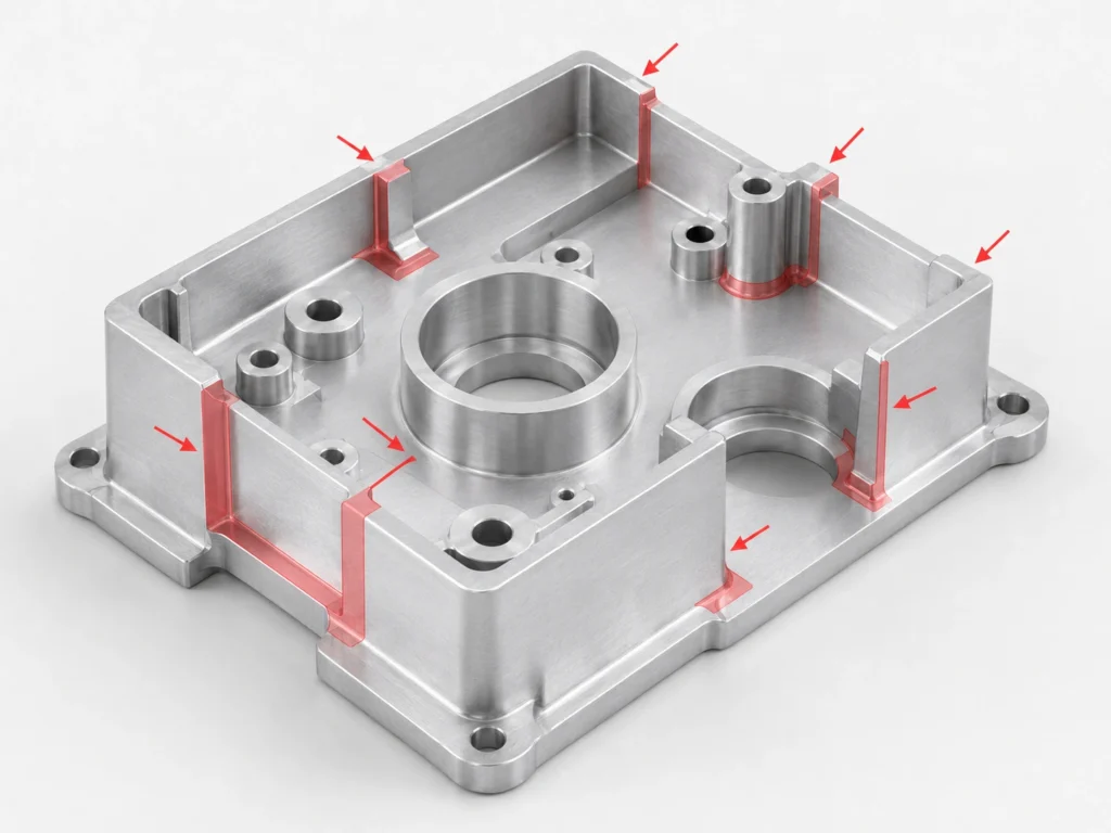
CNC part showing poor design with sudden wall thickness changes

Sudden Thickness Changes

Avoid abrupt wall-thickness changes that can create uneven stiffness, stress concentration, and machining distortion.
CNC machined aluminum part showing excessively thin unsupported walls

Excessively Thin Walls

Very thin walls can flex, vibrate, or deform during machining, handling, and inspection.

Need a Wall Thickness Design Review?

Send us your drawings or CAD files for a DFM review. Our engineering team can assess wall thickness, rigidity, tolerances, machining access, and deformation risk before production.
FAQ

Wall Thickness FAQs

Answers to common questions about wall thickness, thin-wall machining, rigidity, and tolerance design for CNC machined parts.

For aluminum parts, around 1.0 mm can be a practical starting point for many designs. The appropriate minimum depends on material, geometry, wall height, tolerances, and machining conditions.

Yes. Material stiffness, cutting forces, heat sensitivity, and machinability all influence how thin a wall can be machined reliably.

In some cases, yes. Feasibility depends on material, wall height, geometry, tool access, fixturing, tolerance requirements, and surface finish. A drawing review is recommended.

Use consistent wall thickness, add radii and supporting features where appropriate, and avoid unnecessarily tall or unsupported thin sections.

Yes. Tight tolerances on thin features may require more controlled machining, fixturing, and inspection to manage deformation and dimensional variation.