CNC Hole and Thread Design Guidelines

Design holes and threads for reliable machining, proper tool access, and consistent part quality while avoiding unnecessary depth and complexity.
Review Your Design
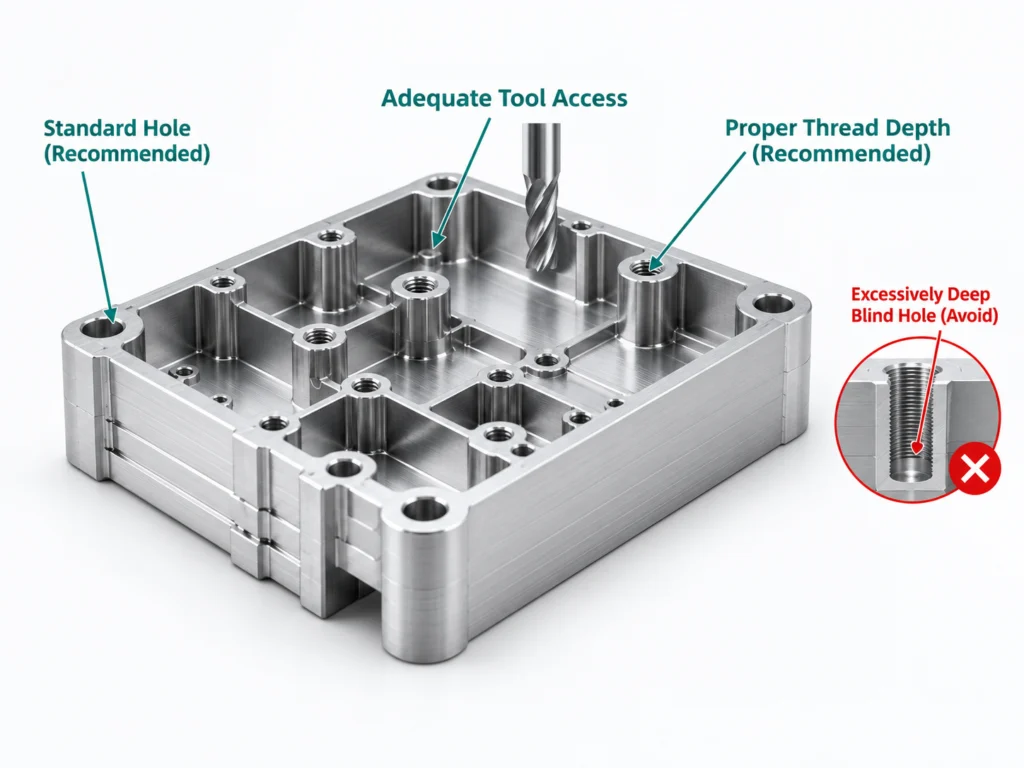
CNC hole and thread design guidelines showing hole depth, thread depth, and tool access
HOLE SIZE & DEPTH REFERENCE

Hole Diameter & Depth Guidelines

Use practical hole diameters and depth-to-diameter ratios to improve machinability, tool access, and machining efficiency.
Hole Diameter (mm)
Typical Application
Typical Depth Guideline
Notes
Ø1–3
Small feature holes
≤ 4× diameter
Use standard sizes
Ø3–6
General purpose
≤ 4× diameter
Deeper holes may need peck drilling
Ø6–12
Clearance / mounting
≤ 4× diameter
Avoid unnecessary deep holes
> Ø12
Large holes
≤ 3× diameter
Consider milling or step drilling
Hole Depth Best Practice
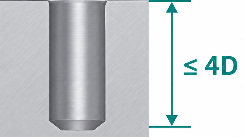
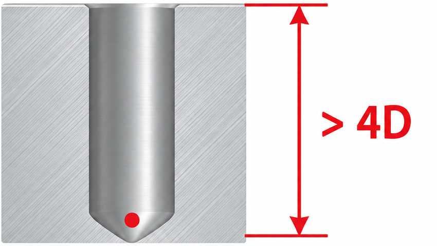
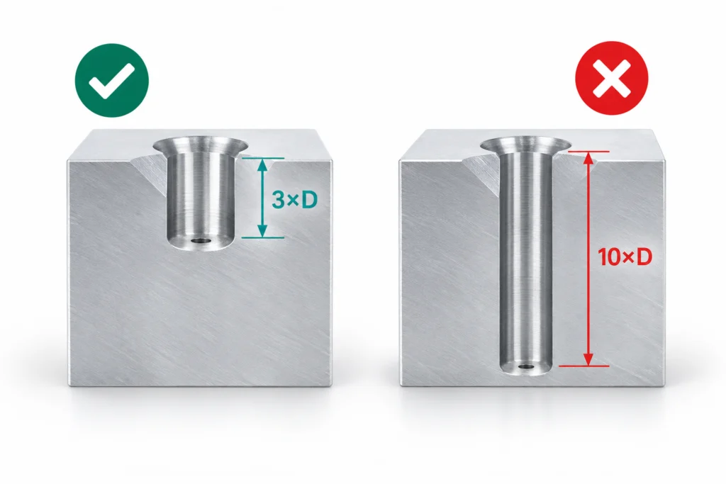
CNC hole depth design comparison showing recommended and excessive depth-to-diameter ratios
Recommended
Avoid
THREAD DESIGN RULES

Design Threads for Reliable Performance

Use standard threads, proper engagement length, and adequate clearance for reliable machining and assembly.

Standard Threads

Use standard metric, UNC, or UNF thread sizes whenever possible.

Thread Engagement

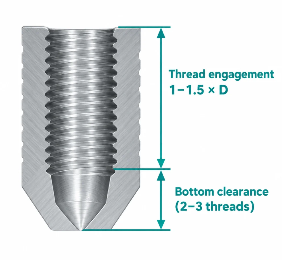
1–1.5× the nominal diameter is a practical starting point for many applications.

Bottom Clearance

Leave extra depth below the thread for drill point and tapping clearance.

Thread Runout

Avoid threading to the very bottom of blind holes unless required.

Thread in Blind Hole

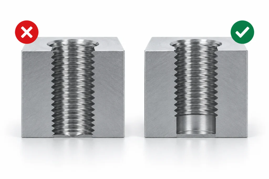
Blind hole thread design showing recommended thread engagement and bottom clearance
DESIGN EXAMPLES

Good vs. Poor Hole & Thread Design

Compare recommended and poor designs to improve CNC manufacturability.
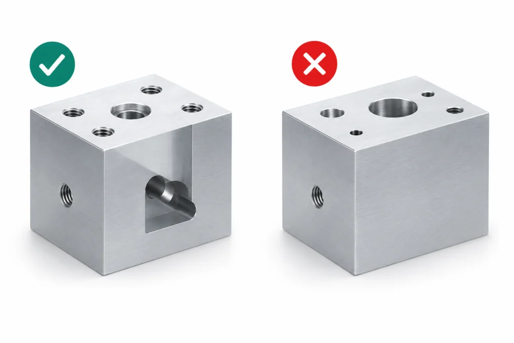
Comparison of standard and non-standard hole sizes for CNC machining

Standard Hole Sizes

Use standard drill sizes instead of unnecessary custom diameters.
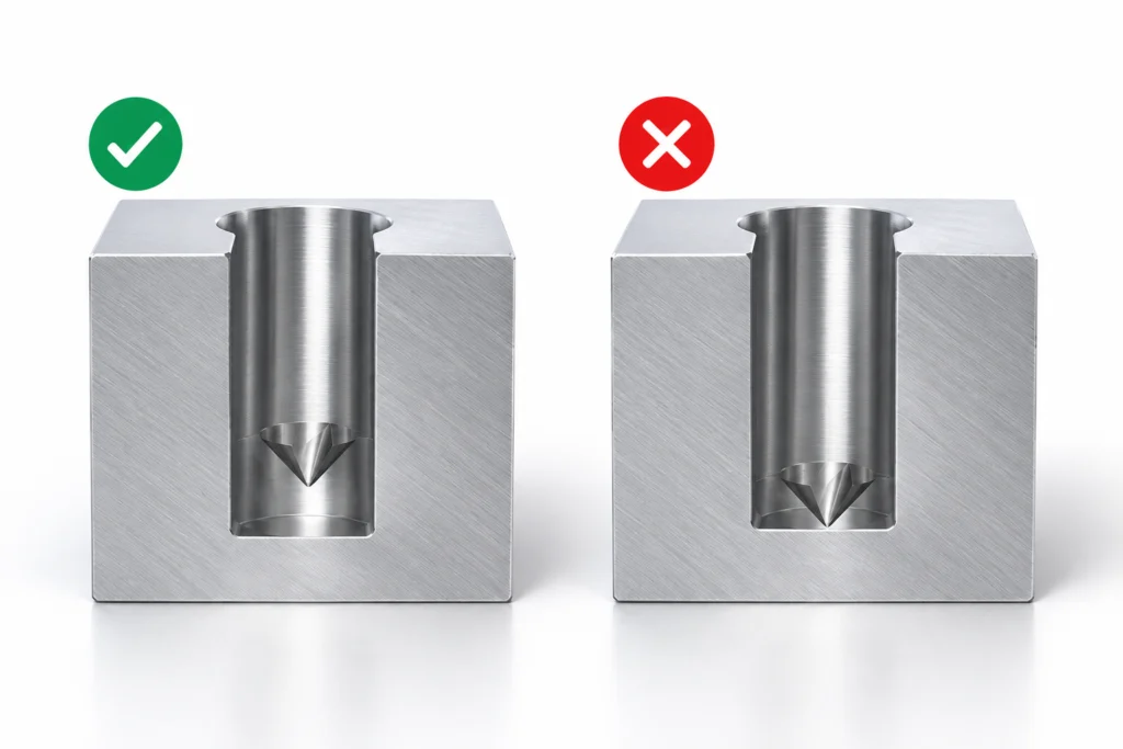
CNC blind hole design comparison showing proper bottom clearance for drilling

Proper Blind Hole Clearance

Leave bottom clearance for the drill point and chip evacuation.
Comparison of practical and excessive hole depth for CNC machining

Practical Hole Depth

Keep depth reasonable to reduce tool deflection and machining difficulty.
Blind hole thread comparison showing proper thread clearance at the bottom

Proper Thread Clearance

Avoid full threads to the bottom of blind holes unless required.
MACHINING CONSIDERATIONS

Key Points for Successful Machining

Follow these practical guidelines for more reliable drilling and threading.
Use standard hole and thread sizes.
Keep depth-to-diameter ratios within practical limits.
Allow sufficient clearance for drilling and tapping.
Avoid unnecessarily deep holes and full-depth threads.
Provide clear tool access whenever possible.
CNC machining center drilling precision holes in an aluminum component

Need a Hole & Thread Design Review?

Send us your drawings or CAD files. We can review hole depth, thread specifications, tool access, and blind-hole clearance.
FAQ

Hole & Thread Design FAQs

Common questions about hole and thread design for CNC machined parts.

As a general design starting point, hole depths up to about 4× the diameter are typically easier to machine with conventional drilling. Deeper holes may require longer tooling, improved chip evacuation, or specialized machining strategies.

Blind holes should include additional depth beyond the required functional depth to allow room for the drill point, chips, and tool clearance.

A thread engagement of around 1–1.5× the nominal diameter is a common starting point. The required engagement depends on material strength, load, thread type, and application requirements.

Yes, but deep small-diameter holes may require special tooling and machining strategies. Tool deflection, chip evacuation, tolerance, and surface finish become more difficult as the depth-to-diameter ratio increases.

Whenever possible, standard drill and thread sizes are recommended because they simplify tooling, inspection, and machining while helping reduce cost and lead time.