A Burr Is a Sign of How the Material Was Cut
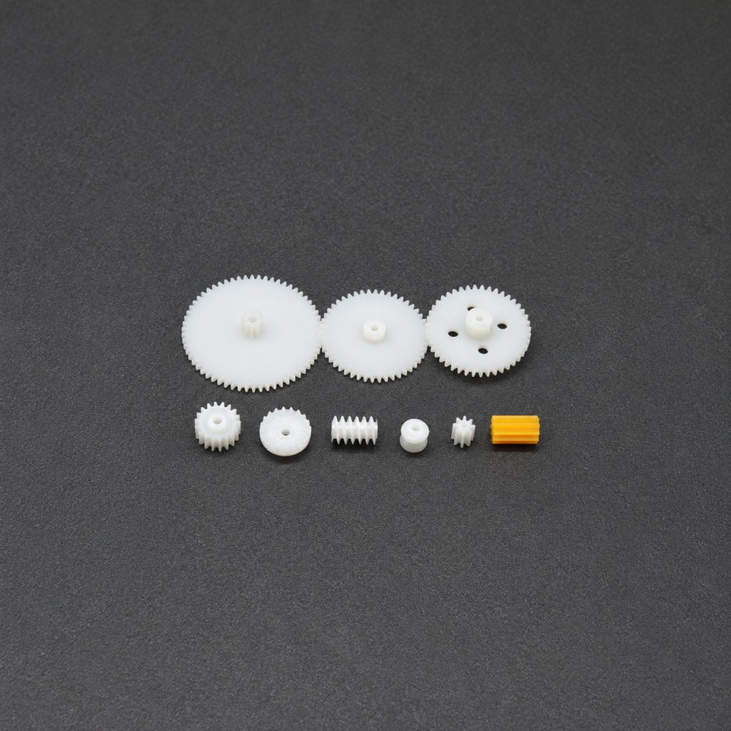
Burr control in POM precision gear machining should begin at the cutting edge rather than at the deburring station. When a sharp tool shears POM cleanly, only limited finishing should be required. Large or stretched burrs usually indicate rubbing, tool wear, excessive heat, poor support, or an unsuitable exit path.
POM has good machinability and dimensional stability, which makes it suitable for gears, rollers, and motion components. However, its toughness and elastic recovery allow thin material to bend away from the tool instead of separating cleanly.
The position and shape of the burr often reveal the source of the problem.
Read the Burr Location
Burrs concentrated on one side of every tooth may indicate cutter runout, misalignment, or an uneven cutting load. Burrs at the tooth end are often related to the tool leaving an unsupported edge.
Thin, curled burrs commonly develop when the cutting edge is no longer sharp enough. Thick, smeared material can indicate excessive heat or rubbing. Irregular fragments inside the tooth root may result from recutting chips.
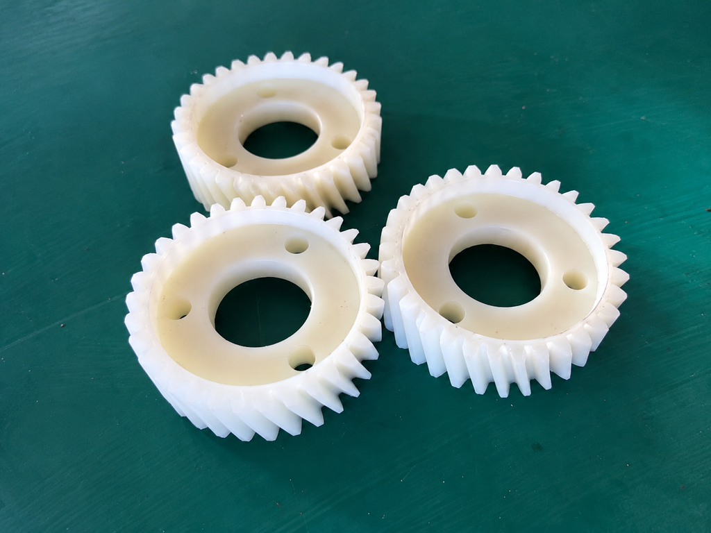
Instead of increasing deburring time, inspect the cutter, holder, workholding, and toolpath whenever the burr pattern changes.
Sharp Tools Need a Real Cutting Load
Tools for POM should have sharp, smooth cutting edges, positive cutting geometry, and sufficient clearance to prevent the tool body from rubbing against the plastic.
A very low feed is not always safer. If chip thickness becomes too small, the tool may rub and heat the surface rather than cut it. Excessive feed, however, can deflect the gear blank or tear the tooth edge.
The cutting parameters should create a stable chip without melting, fuzzing, or deforming the profile. Tool life limits should be based on measured burr growth and gear quality, not only on catastrophic cutter failure.
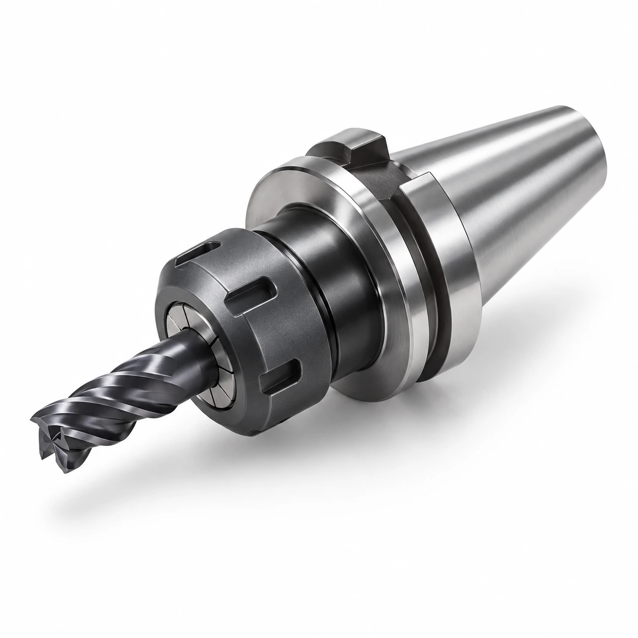
For fine-pitch gears, even small cutter runout can change the load on individual teeth. Short tool overhang, accurate holders, rigid fixturing, and balanced cutters improve consistency.
Plan the Tool Exit Before Cutting
Many gear burrs form where the cutter exits the material. The last layer of unsupported POM can bend outward and remain attached to the tooth edge.
Where the geometry permits, provide support near the exit surface or use a sacrificial backing feature. Toolpath direction and cutter engagement should be tested to identify which approach produces the cleanest edge without causing tooth deflection.
A small engineered chamfer may be added before or after tooth cutting when the drawing allows it. This is more repeatable than removing an undefined edge manually. The chamfer must not reduce the required tooth contact area or change the functional profile.
Remove Chips Before They Return to the Cut
Continuous chip evacuation is essential because light POM chips can remain around the cutter and enter the tooth space again. Recut chips increase heat, scratch the surface, and create secondary burrs.
Compressed air, vacuum extraction, or an application-compatible coolant can help keep the cutting zone clear. Coolant should not be used as a substitute for sharp tooling or correct parameters.
The process must also avoid local overheating. Warning signs include glossy smeared areas, discoloration, softened edges, and chips that appear melted rather than cleanly cut.
Hold the Blank Without Distorting It
POM can deform under excessive clamping pressure and recover after removal from the fixture. If the blank changes shape during cutting, tooth thickness and runout may shift even when the machine program is correct.
Use broad, controlled contact areas and enough support to resist cutting forces without crushing the part. For thin gears, the fixture should support the face while keeping finished tooth surfaces free from clamp damage.
Material conditioning and rough-machining strategy may also be important for thick stock or parts with substantial material removal.
Deburr Without Changing the Gear Profile
Deburring must remove loose material while preserving the tooth tip, root radius, flank geometry, and surface finish. Aggressive sanding or uncontrolled tumbling can round tooth edges and alter backlash.
Manual trimming under magnification is suitable for prototypes and low quantities. Controlled brushing or automated edge finishing may be used for production after the process has been validated on functional dimensions.
Inspection should include magnified visual checks, tooth thickness or profile measurement, runout, and a functional mesh test with the mating gear. A visually clean gear is not acceptable if deburring has changed how the teeth engage.
Stable POM gear production comes from preventing burrs during cutting and using finishing only for small, predictable remnants.