
A low-inertia laser galvanometer mirror mount allows the scanner motor to accelerate, reverse, and settle the mirror more quickly. This directly affects marking speed, corner accuracy, line quality, and the time required to move between processing points.
However, the low-inertia requirement applies mainly to the mirror holder or bracket that rotates with the galvanometer shaft. A stationary bracket supporting the scanner housing has different priorities, including stiffness, thermal stability, and vibration isolation.
A Scan Command Begins with Acceleration
A galvanometer scanner is a limited-rotation motor with a mirror attached to its rotor. The control system continuously commands angular positions so the reflected laser beam follows a programmed path.
The motor must accelerate the rotor, mirror, adhesive, and rotating mount together. Their combined moment of inertia determines how much torque is required to achieve a given angular acceleration.
Reducing inertia allows the same motor to change mirror angle more rapidly. Alternatively, the scanner can achieve the required motion with less peak current and lower mechanical loading.
This relationship becomes especially important in laser marking, micromachining, PCB drilling, medical imaging, and additive manufacturing, where the mirror may reverse direction thousands of times during a job.
Mass Far from the Shaft Has the Greatest Effect
Rotational inertia depends not only on total mass but also on where that mass is positioned. Material located far from the rotational axis contributes much more inertia than the same mass close to the shaft.
A mirror mount can therefore be relatively light and still perform poorly if it has thick outer edges, long arms, or unnecessary fasteners positioned away from the axis.
Effective design removes material from the outer regions while retaining enough structure around the shaft connection and mirror support. Pockets, ribs, tapered sections, and compact bonding areas may be used to place material only where it contributes useful stiffness.
Simply selecting a low-density material does not guarantee a low-inertia assembly. Geometry and mass distribution must be evaluated together.
Lower Inertia Reduces Tracking Error
The mirror cannot respond instantly to a command. During rapid movement, its actual position may lag behind the requested position. This difference is known as tracking error.
Excessive tracking error can round corners, narrow circular features, distort characters, or cause adjacent scan lines to overlap incorrectly. The effect becomes more visible as scanning speed and acceleration increase.
Scanner control software can compensate for part of this behavior, but compensation cannot remove the physical limits of an overloaded rotor. SCANLAB notes that galvanometer motors and mirrors must be matched to the inertial load, while scanner specifications commonly define recommended and maximum allowable inertia.
A lighter mirror mount gives the control loop more dynamic margin and makes precise trajectory correction easier.
Settling Determines When the Laser Can Fire
After a rapid position change, the rotating assembly may overshoot or oscillate before reaching a stable angle. The laser must often remain off until this motion falls within the permitted position tolerance.
A high-inertia mount can increase settling time, reducing production throughput even if the scanner reaches a high maximum velocity. Residual vibration may also create hooks at line starts, enlarged dots, or inconsistent energy deposition.
Low inertia helps the motor stop the mirror more quickly, but stiffness and damping remain necessary. A mount that is extremely light but flexible can introduce structural vibration and produce worse settling behavior than a slightly heavier, rigid design.
The engineering target is therefore low inertia with a natural frequency safely above the scanner’s working bandwidth.
Motor Current Becomes Heat
More torque generally requires more motor current. Repeated acceleration of a heavy rotating assembly increases electrical and thermal loading in the galvanometer.
Additional heat can change coil resistance, bearing conditions, sensor output, adhesive properties, and the dimensions of the scanner structure. The resulting thermal drift may shift the laser position during a long production run.
Lower rotating inertia reduces the torque demand for the same scan trajectory. This can limit heat generation and improve long-term positional stability, although the complete thermal design must also consider laser absorption by the mirror and heat transfer through the shaft.
The Material Must Be Light and Stiff
A suitable mirror-mount material requires more than low density. It must provide adequate specific stiffness, fatigue resistance, dimensional stability, and reliable attachment to the shaft and mirror.
Aluminum alloys are commonly considered because they combine low density, machinability, and useful stiffness. Titanium may be selected when strength, temperature resistance, or joint durability is more important, although its higher density can increase inertia. Magnesium and composite materials offer lower density but introduce additional concerns involving corrosion, coating, anisotropy, cleanliness, and manufacturing control.
Thermal expansion must also be compatible with the mirror, shaft, and adhesive. A large expansion mismatch can deform the mirror or shift its angle as temperature changes.
Balance Matters as Much as Weight
An unbalanced mount produces cyclic bearing loads and vibration whenever it changes direction. These forces can reduce bearing life, disturb position feedback, and affect repeatability.

The mount should therefore be designed around the actual center of rotation and evaluated together with the mirror and bonding material. Adhesive thickness variation, asymmetric pockets, coating distribution, and machining tolerances can shift the center of mass.
For high-performance scanners, inspection may include mass measurement, center-of-gravity control, dynamic balance, bond-line verification, and dimensional inspection of the shaft interface.
Do Not Lighten the Stationary Support Blindly
The external bracket holding the galvanometer housing does not rotate with the mirror. Reducing its mass provides little direct improvement in rotor acceleration.
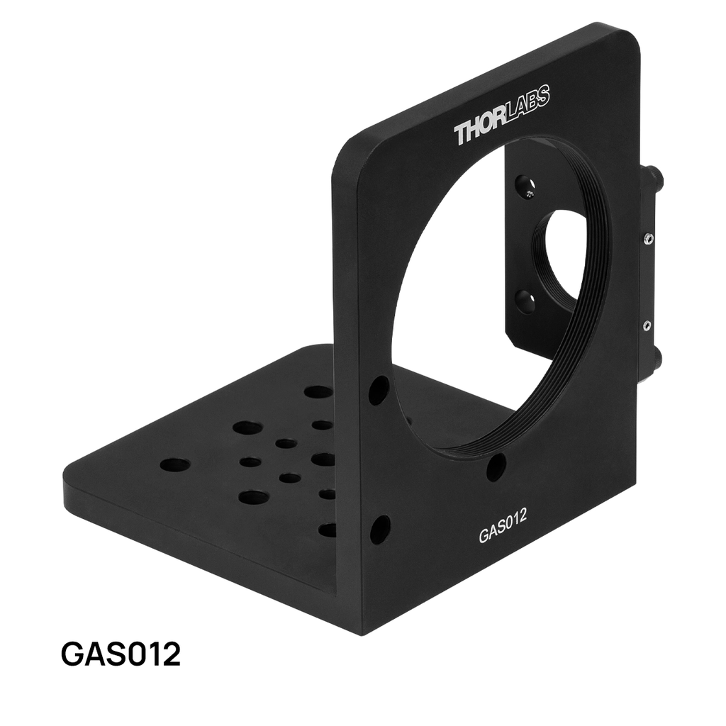
This stationary bracket usually needs high rigidity so the scanner axes remain aligned with the lens and work surface. If it is made too thin, machine vibration and thermal movement can shift the beam even when the galvanometer itself is operating correctly.
The correct approach is to minimize inertia in the rotating mirror assembly while maintaining stiffness and thermal stability in the stationary support.
Performance Must Be Verified as an Assembly
Material density alone cannot predict scanner performance. The final evaluation should use the complete mirror, mount, shaft, motor, position detector, and servo controller.
Step-response time, overshoot, settling time, tracking error, resonant frequency, thermal drift, and scan-pattern accuracy provide more useful evidence than component weight by itself.
A successful mirror mount is not merely the lightest part that can be manufactured. It places minimal mass away from the rotational axis while preserving stiffness, balance, thermal stability, and a dependable connection to the mirror and shaft.