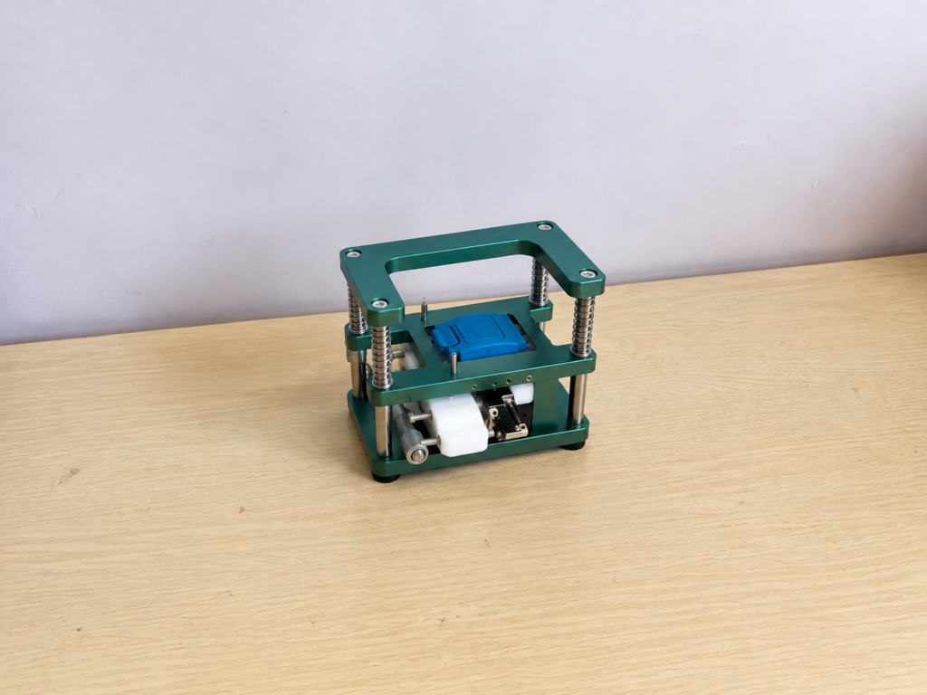
Workholding fixture wear reduction begins by identifying where pressure, sliding, vibration, and chips occur during loading and clamping. Locating points, clamp interfaces, and guide components experience different wear mechanisms, so they should not receive the same treatment.
Identify the Wear Mechanism
Wear marks show how the fixture is operating. Polished tracks usually indicate sliding, dents suggest excessive contact pressure, and shallow pits may result from fretting caused by small movements between clamped surfaces.
Scoring and transferred material indicate adhesive wear, while deep scratches often come from trapped chips. Before selecting a coating, examine the contact area, clamping force, movement direction, cycle frequency, and mating material.
Reduce Sliding and Contamination
Even a hard surface will wear if every workpiece is dragged across it. Lead-in features, relieved areas, rollers, or controlled loading paths can reduce unnecessary contact. Clamps should press the workpiece against the locators without pulling it sideways.
Chip control is equally important. Metal particles trapped on locating surfaces create concentrated pressure, scratch components, and alter positioning accuracy. Air-cleaning ports, drainage grooves, and accessible cleaning areas help keep critical contacts clear.
Match Treatments to Wear Zones
Fixture components should be treated according to their function.
Locating pins and steel supports can use hardening or nitriding to improve wear resistance with limited dimensional change. Thin PVD or DLC-type coatings may suit sliding contacts that require high hardness and lower friction, provided the substrate is sufficiently hard and properly prepared.
Electroless nickel offers uniform coverage and can improve wear and corrosion resistance on complex parts. Aluminum fixture bodies may use hard anodizing, but heavily loaded locating points are usually better equipped with hardened-steel inserts because concentrated impact can damage the anodized layer.
Coating thickness must be included in the dimensional specification, especially around precision fits, holes, and locating surfaces.
Use Replaceable Contact Components
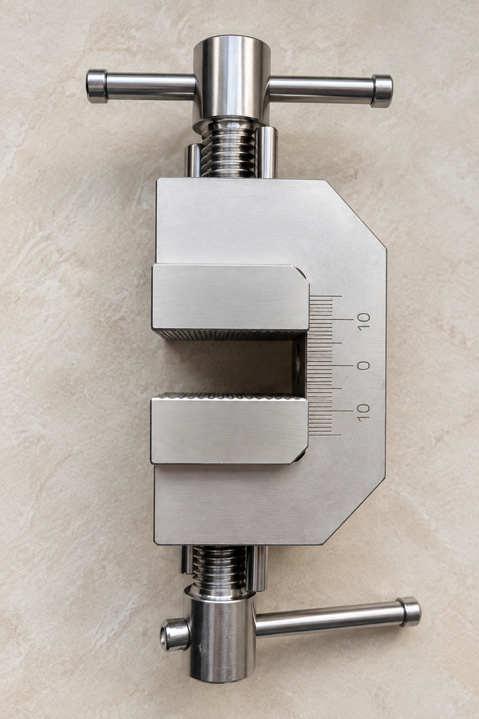
High-wear surfaces should not always be machined directly into the fixture body. Replaceable pads, bushings, wear strips, and locator inserts allow damaged areas to be renewed without rebuilding the complete fixture.
These components must be firmly supported and accurately located. Their thickness and mounting tolerances should be controlled so replacement does not change the workpiece datum.
For delicate workpieces, maximum hardness may not be appropriate. Bronze, polymer, or engineered-composite contact pads can protect the component while providing acceptable fixture life. The objective is to reduce wear across the entire contact pair.
Control Clamping Force
Excessive force causes indentation, coating damage, and fixture deformation. Insufficient force allows vibration and fretting. The fixture should apply the lowest force that can securely resist machining loads.
Clamp pads must contact the workpiece evenly. Misalignment can concentrate the load on a narrow edge and cause rapid wear. Lubrication may help suitable sliding mechanisms, but it should not contaminate datum surfaces or reduce holding stability.
Establish Maintenance Limits
Fixture maintenance should be based on dimensional change rather than appearance alone. Regular checks should cover locator height, pin diameter, guide clearance, pad flatness, and clamp alignment.
Cycle counts can determine inspection intervals, but measured wear should decide when parts are replaced. Representative wear testing can also compare material and coating combinations before full production.
Conclusion
Frequently used fixtures last longer when wear is controlled through better loading paths, clean contact surfaces, suitable treatments, and replaceable wear parts. A practical system combines a rigid fixture body, hardened locators, protected sliding surfaces, and routine dimensional inspection.